
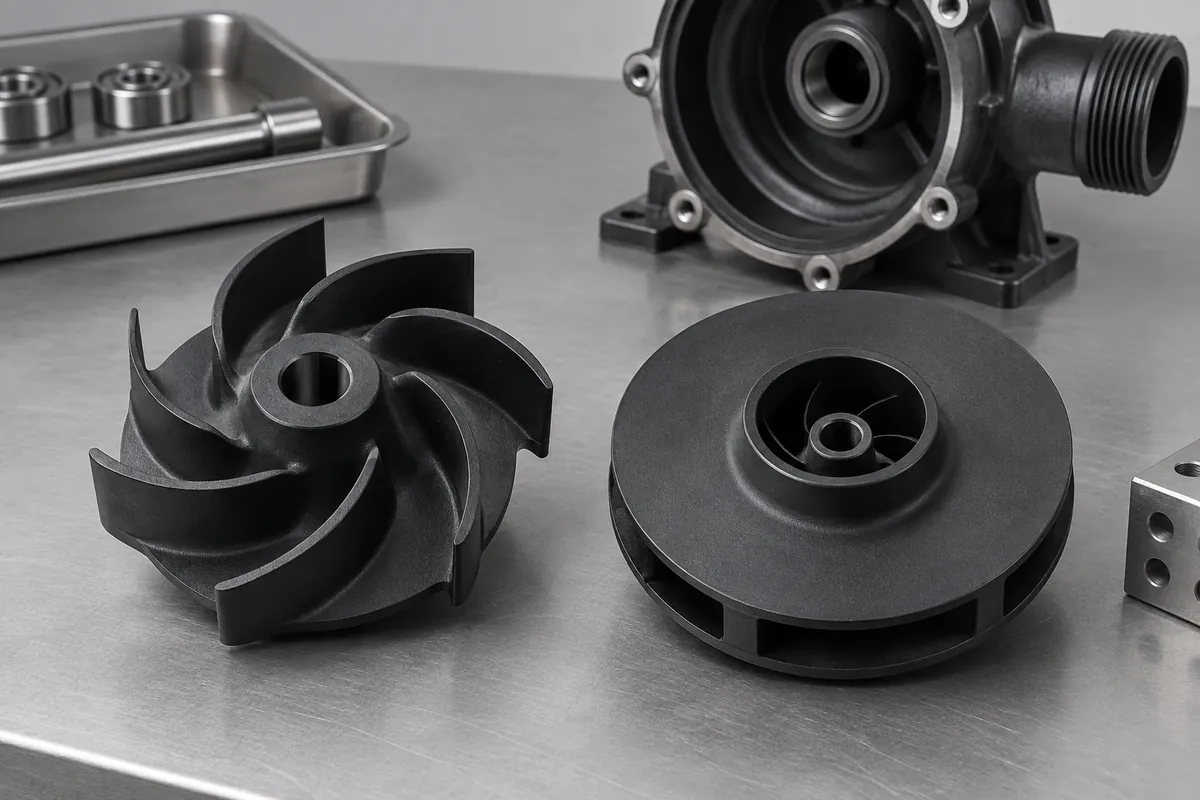
Product design illustrations. Final geometry, materials and acceptance criteria are project-specific.
An open impeller exposes its blade passages, while a closed construction adds a shroud that changes both the hydraulic geometry and the manufacturing problem. The best choice depends on the pump system and fluid duty. It should not be made solely because one shape appears more complete or easier to clean in a rendering.
Separate hydraulic selection from manufacturing feasibility. The pump designer must define the required flow path and operating envelope. The molding review then determines how that geometry can be produced, inspected and assembled without silently changing the surfaces that influence pump behavior.
Understand the enclosed geometry
An open blade arrangement can provide more direct access to molded surfaces, but release still depends on draft, blade curvature and the chosen tool direction. A curved or locally undercut blade can require a more involved tool than its open appearance suggests. Review the complete three-dimensional shape.
A closed passage may prevent a conventional rigid core from withdrawing. One possible route is to mold a bladed back section and a separate cover, then join them. Other tooling approaches require their own feasibility assessment; the existence of a closed plastic impeller does not prove a universal one-shot molding method.
The KSB impeller overview provides pump-design context. Manufacturing decisions should preserve the hydraulic intent while acknowledging the additional interfaces introduced by a split and joined construction.
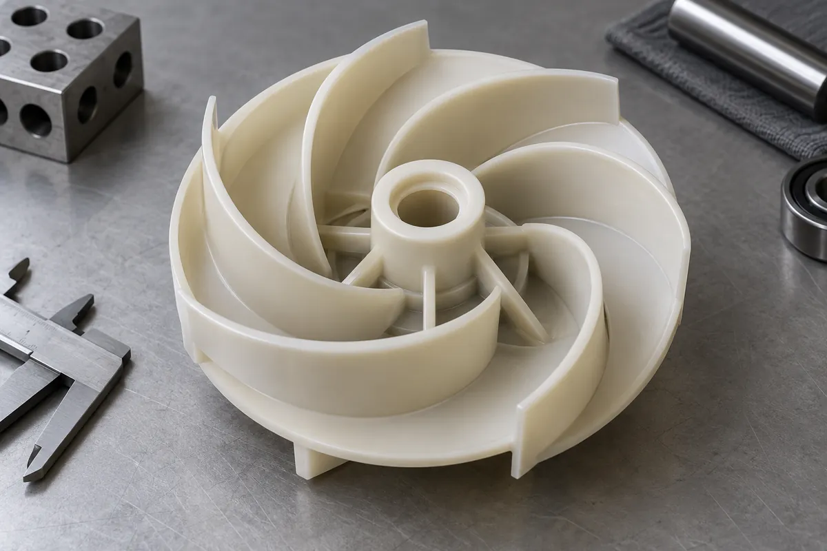
Treat a joined impeller as an assembly
If the impeller is split, decide where the joint belongs before tool design is finalized. Locating features, joining surfaces and any energy director or weld preparation occupy real space. They should not obstruct the intended passages or create uncontrolled flash in a region that is difficult to inspect afterward.
Specify how the two sections are aligned during joining. A small offset can alter the blade exit or create imbalance even when each molded half passes its individual dimension checks. The fixture and the references used to locate the assembly are therefore part of the manufacturing definition.
Decide which dimensions are finalized after joining. Bore finishing or balance correction may need to follow assembly so the inspection reflects the delivered state. Do not compare an unfinished molded half with a finished welded impeller as though they were equivalent supply items.
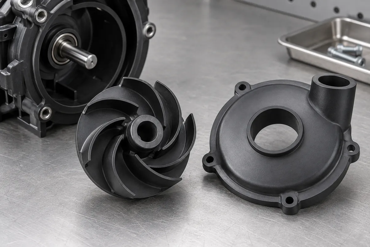
Plan inspection before access disappears
Identify internal features that cannot be measured conveniently after the cover is installed. Some checks may need to occur before joining, with traceability linking the two sections to the finished assembly. Other requirements may need an agreed indirect or destructive method for development samples.
Keep joint integrity separate from cosmetic appearance. An even-looking external seam does not establish the strength or sealing behavior required in service. Define the relevant joint evaluation and its sample scope rather than relying on a photograph of the outside of the component.
Consider cleaning and loose particles within the passages. Trimming debris or joining flash can become a system issue even when it has little effect on the external dimensions. Agree the cleanliness requirement and inspection access for the actual fluid application.
Consider how the finished assembly will be traced if either molded half comes from multiple cavities. Pairing records or another controlled identification method can help investigate a later joint or balance issue. The traceability should follow the delivered impeller without placing markings where they interfere with the flow path or rotating clearance.
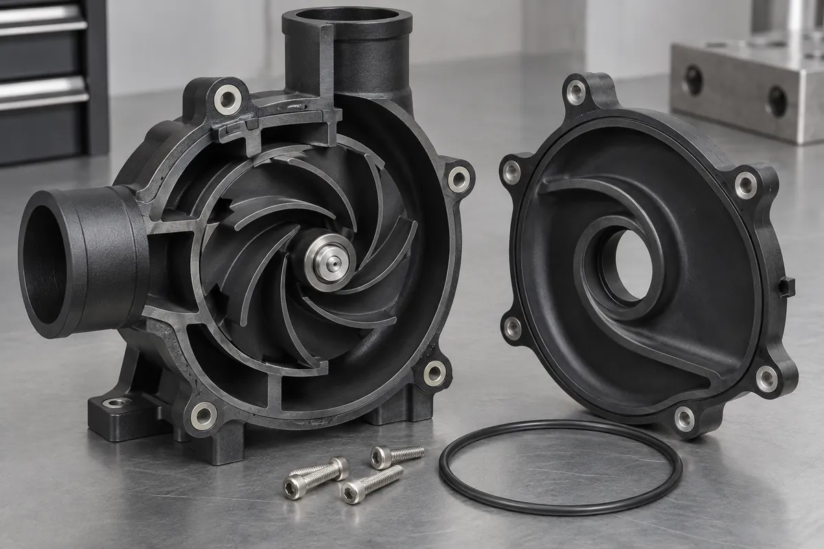
Compare the complete delivered configuration
Cost comparisons should include molding, joining, fixtures, finishing, inspection and development approval. A split design may simplify some tooling while adding assembly work. A more complex tool may avoid a joint but create different maintenance and inspection demands. Neither route is universally cheaper.
Connect the review to pump assembly validation. The finished component must be assessed in its intended system; an accurate replica of the nominal geometry does not establish the full pump curve or duty-life performance.
Record whether the approved item is an open molded component, a joined closed assembly or another defined construction. This avoids a later supplier interpreting the same drawing as a different manufacturing route and changing the evidence needed for production release.
Discuss the component and its acceptance requirements
Explore our custom plastic impellers and the related project case study. Send the current drawing, mating-part details, operating conditions and required quantities. We can review tooling, molding and inspection as a defined supply scope, with development samples and production approval kept separate.