
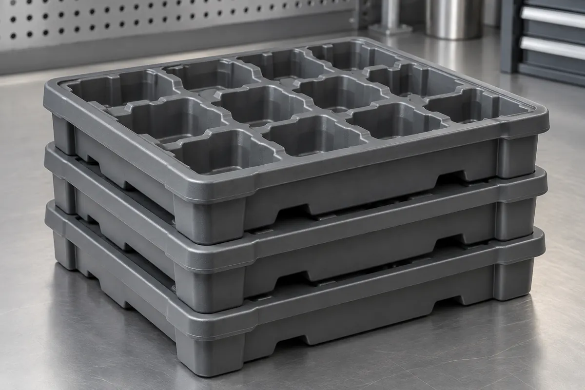
Product design illustrations. Final geometry, materials and acceptance criteria are project-specific.
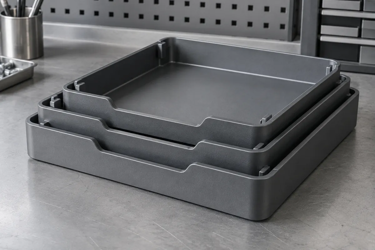
Stacking and nesting are related but different functions. Loaded stacking keeps trays apart to protect their contents and carry vertical load. Empty nesting reduces return volume by allowing trays to overlap. A design that does one well may need additional features to perform the other without jamming or damaging components.
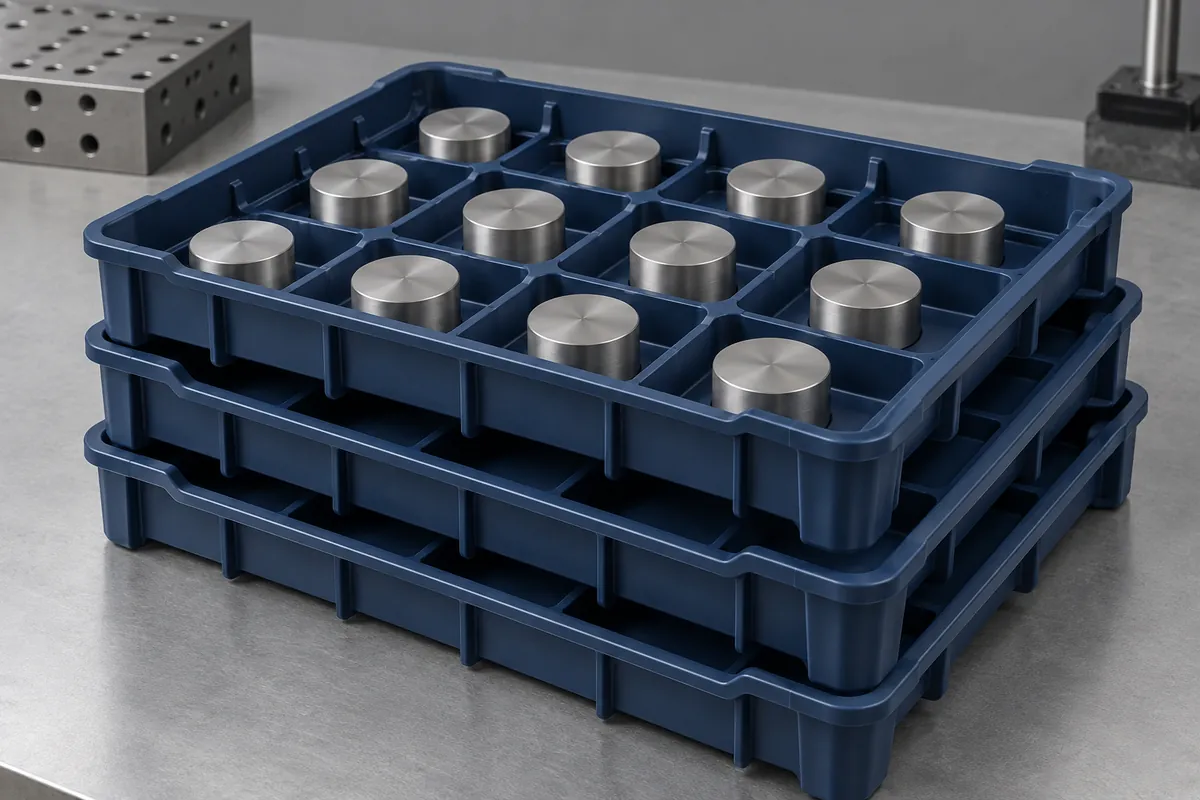
Define the complete stack arrangement, including the bottom support and any top restraint. Record how many trays are loaded, how the load is distributed and how the stack moves. The geometry of a single tray cannot establish the behavior of a tall stack on a different rack or conveyor.
Trace the structural load path
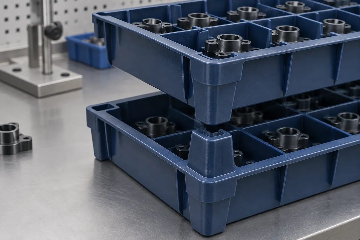
Identify the feet, rims or columns that transfer weight between trays. Avoid relying on the carried components as unintended supports. If the tray base deflects, verify that it remains clear of the parts below. Loaded clearance matters more than the nominal separation shown in an unloaded section view.
Check the bottom tray under the full stack load and its actual support spacing. A broad benchtop supports the base differently from two narrow rack rails. Include any overhang, local stop or conveyor transfer that can change the load distribution. These conditions should accompany a reported deflection result.
Ribs can help establish a more useful load path, but their geometry requires a molding review. Protolabs discusses rib and gusset construction. Apply the design reasoning to the actual tray rather than assuming that more or thicker ribs always improve the result.
Provide controlled nesting and separation
Choose where an empty tray stops as it enters the next one. Without a positive nesting stop, tapered walls may wedge under handling load. A stop also helps maintain access for fingers or a mechanical separator. Verify that tolerance variation does not allow a deeper, unintended seating position.
Review air escape where closely fitted surfaces approach each other. A trapped volume or a large smooth contact area can make separation inconsistent. The appropriate relief depends on the geometry and the cleanliness requirement; do not add an opening that defeats the tray's protective function.
Test the actual de-nesting direction and equipment. A manual sideways twist can release trays that a vertical automated motion cannot separate. If the production line uses a separator blade or gripper, provide the required access and keep it away from loaded-component contact areas.
Include time and handling in validation
Measure loaded deflection after a defined hold time and at the relevant temperature. An immediate reading and a long storage result describe different conditions. Also inspect recovery after unloading when a tray must return to an accurate loading fixture.
Evaluate lateral stability during the intended transport events. A stable static stack may shift during acceleration, braking or transfer. Locating features must balance resistance to unwanted movement with practical stacking and unstacking. Excessive engagement can make normal handling difficult or damage corners.
Record the number of stacks and trays actually tested. A result from five carriers does not prove every unit in a large delivery meets the same load requirement. Keep development evidence, routine sampling and the released operating limit as separate parts of the documentation.
Maintain compatibility as the system evolves
If old and new tray revisions must stack together, include both combinations in the approval. A small change to rim height or a nesting stop can create a mixed-stack problem that is invisible when only matching new trays are tested. Mark incompatible revisions clearly in the handling system.
Set replacement criteria for damaged feet, rims and locating corners. A tray that still holds a component can be unsafe or unreliable within a loaded stack. Maintenance decisions should reflect the shared load path rather than only the condition of the pockets.
Review material and exposure conditions alongside the geometry. Release the stacking arrangement, support method, load distribution and separation sequence together so operators and suppliers use the same definition of acceptable performance.
Discuss the component and its acceptance requirements
Explore our custom component trays and the related project case study. Send the current drawing, mating-part details, operating conditions and required quantities. We can review tooling, molding and inspection as a defined supply scope, with development samples and production approval kept separate.