

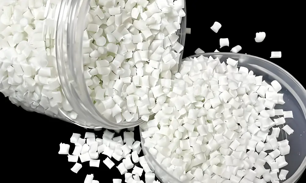
| Glass-filled nylon is polyamide (PA6 or PA66) compounded with 15–50% chopped glass fibre by weight. The fibers bond to the PA matrix through silane-sized coupling agents, transferring load from the weaker polymer to the stiffer fiber. The result: tensile strength increases from ~80 MPa to 170–245 MPa, heat deflection temperature rises from 90°C to 240–265°C, and shrinkage falls from 1.5–2.5% to 0.2–1.5% — but becomes anisotropic. |
Glass-filled nylon is one of the most widely molded engineering materials globally — used in automotive under-hood components, electrical connectors, structural brackets, and power tool housings wherever unfilled nylon’s stiffness or heat resistance is insufficient.
The engineering trade-offs are equally significant. This guide covers both the benefits and the constraints with the quantitative data engineers need.
What Happens When Glass Fiber Is Added to Nylon?
Nylon (polyamide) in its unfilled state is a tough, fatigue-resistant, and chemically resistant engineering polymer — but its stiffness and elevated-temperature performance are limited by its semi-crystalline structure and relatively high moisture absorption. Glass fiber reinforcement addresses both limitations simultaneously.
The Reinforcement Mechanism
Glass fibers are not simply mixed into nylon — they are chemically bonded to the PA matrix. The fibers are pre-coated with a silane-based coupling agent (sizing) that forms covalent bonds between the silanol groups on the glass surface and the amine end-groups of the polyamide chain.
This interface bond is what allows stress transfer from the compliant polymer matrix to the stiff glass fiber — without it, the fibers would simply act as voids and reduce properties rather than improving them.
Chopped glass fibers used in injection molding grades are typically 3–6 mm in length as supplied — but shear in the barrel and gate reduces fiber length during processing to 200–500 µm in the molded part. Preserving fiber length through gentle plastication and large gates is the primary mechanical property optimization lever in GF nylon processing.
Why Fiber Alignment Causes Anisotropy
As GF nylon melt flows into the mold cavity, fibers align progressively with the flow direction. In the center of the flow (away from the walls), fibers align nearly parallel to the flow path. Near the walls, shear forces create a skin layer where fibers are also highly oriented. The result: the molded part has significantly higher stiffness parallel to flow than perpendicular to it.
This fiber orientation also governs shrinkage. Where fibers are aligned (flow direction), they physically resist the polymer matrix from contracting — shrinkage is 0.2–0.5%. Perpendicular to the fibers (cross-flow direction), the matrix contracts more freely — shrinkage is 0.8–1.5%.
The 3–5× differential between these two directions is the physical cause of warpage in GF nylon flat panels and the primary reason mold flow simulation is not optional for GF nylon programs.
The Weld-Line Limitation — A Critical Design Constraint
Weld lines form where two melt fronts meet after flowing around a core pin or obstruction. At a weld line, fibers cannot cross the meeting plane — they arrive from both sides and remain parallel to the weld surface rather than bridging across it. The practical consequence: weld-line strength in glass-filled nylon is approximately equal to unfilled resin strength, regardless of GF content.
Glass-Filled Nylon vs Unfilled Nylon: Property Comparison
The table below quantifies the property changes from glass fiber reinforcement using PA66 as the baseline resin, comparing unfilled PA66 to GF30 and GF50 grades at standard test conditions (ASTM D638 / ISO 527). [3]
| Property | Unfilled PA66 | Glass-Filled PA66-GF30/GF50 |
| Tensile strength | PA66 unfilled: 70–85 MPa | PA66-GF30: 170–190 MPa (+125%) PA66-GF50: 200–245 MPa (+190%) |
| Flexural modulus | PA66 unfilled: 2.5–3.0 GPa | PA66-GF30: 9–12 GPa (3–4× stiffer) PA66-GF50: 14–18 GPa (5–6× stiffer) |
| Heat deflection temp (1.82 MPa) | PA66 unfilled: 60–90°C (dry/conditioned) | PA66-GF30: 240–260°C PA66-GF50: 255–265°C |
| Shrinkage | PA66 unfilled: 1.5–2.5% (isotropic) | PA66-GF30: 0.2–0.5% flow / 0.8–1.5% cross-flow Anisotropic — simulation mandatory |
| Moisture absorption (24h, 23°C) | PA66 unfilled: 2.5–3.0% | PA66-GF30: 1.5–2.0% (GF reduces absorption ~30%) |
| Impact resistance (notched Izod) | PA66 unfilled: 5–8 kJ/m² | PA66-GF30: 8–12 kJ/m² (moderate improvement) Note: GF does NOT dramatically increase impact — toughness-modified grades add rubber phase |
| Weld-line strength | Base resin strength at weld line | GF weld-line strength = unfilled resin only Fibers do NOT cross weld lines — strength at weld is equivalent to unreinforced PA66 |
| Surface finish | Smooth, fine appearance | Textured/matte surface — glass fibers visible at surface, especially with high GF% or high mold temperature |
| Tool wear rate | Low — standard P20 steel adequate | High — H13 hardened steel (48–52 HRC) mandatory for production tooling |
Key insight from the data: glass fiber dramatically improves stiffness and heat resistance, but does not dramatically improve impact toughness. Engineers seeking both high stiffness and high impact resistance need toughness-modified GF nylon grades — compounds that include both glass fiber for stiffness and rubber (EPDM or SBR) for toughness.
Glass-Filled Nylon Grade Comparison
The five grades below cover the production range available in commercial injection molding. Grade selection depends primarily on the required service temperature, dimensional stability under moisture, and structural load.
| Grade | Key Mechanical Data | Processing Characteristics | Primary Applications |
| PA6-GF30 (Nylon 6 + 30% GF) | Tensile: 130–170 MPa Flex mod: 7–10 GPa HDT (1.82 MPa): 200–210°C Shrinkage (flow / cross): 0.2–0.4% / 0.8–1.2% | Better flow, lower processing temperature, superior toughness. Preferred for geometrically complex parts with long flow paths. Higher moisture absorption (3.5%) than PA66. | Automotive air intake manifolds, connector housings, instrument brackets, complex-geometry industrial housings requiring good impact toughness. |
| PA66-GF30 (Nylon 66 + 30% GF) | Tensile: 170–190 MPa Flex mod: 9–12 GPa HDT (1.82 MPa): 240–260°C Shrinkage (flow / cross): 0.2–0.5% / 0.8–1.5% | Higher stiffness and HDT than PA6-GF. Tighter chain packing gives better creep resistance at elevated temperature. Lower toughness than PA6-GF. Pre-dry mandatory: 80°C / 4–8 h. | Under-hood automotive brackets, electrical connector housings (USCAR-2 rated), power tool housings, structural under-load components above 120°C service. |
| PA66-GF50 (Nylon 66 + 50% GF) | Tensile: 200–245 MPa Flex mod: 14–18 GPa HDT (1.82 MPa): 255–265°C Shrinkage (flow / cross): 0.1–0.3% / 0.6–1.0% | Maximum stiffness and heat resistance in the PA66 series. Very high melt viscosity — requires large gates and hot runner. Weld-line strength approximately equal to unfilled resin base (not GF-reinforced). Tool steel must be H13 48–52 HRC. | Metal-replacement structural brackets, high-load gearbox housings, aerospace structural clips, engine mount insulators. |
| PA12-GF (Nylon 12 + 15–30% GF) | Tensile: 90–140 MPa Flex mod: 4–8 GPa HDT (1.82 MPa): 140–180°C Moisture absorption: 0.25% (lowest of PA family) | Lowest moisture absorption of any glass-filled PA — near-constant dimensions in humid service. Lower stiffness and HDT than PA66-GF. Excellent chemical resistance and flexibility retention. | Fuel system components (automotive), medical tubing connectors, precision instruments requiring humidity-stable dimensions, food-contact structural parts. |
| PA46-GF30 (Nylon 46 + 30% GF) | Tensile: 200–220 MPa Flex mod: 12–15 GPa HDT (1.82 MPa): 280–295°C Barrel temp: 300–330°C | Highest HDT in the polyamide family. Extreme high-temperature structural performance — beyond PA66’s capability. Highly hygroscopic; demanding processing. DSM Stanyl® is the market-leading grade. | Automotive transmissions, torque converter housings, oil-cooled motor end caps — applications requiring PA structural properties above 250°C. |
Grade selection decision tree:
- Service temperature below 150°C, complex geometry, cost-sensitive: PA6-GF30 — best flow, lowest tooling requirement, adequate for most industrial and connector applications.
- Service temperature 150–250°C, structural load, good moisture stability: PA66-GF30 — the most widely molded engineering grade globally.
- Maximum stiffness, service temperature > 200°C, metal replacement: PA66-GF50 — requires H13 hardened tooling and hot runner system. Gate area tungsten carbide inserts recommended.
- Precision dimensions in humid service, chemical exposure: PA12-GF — lowest moisture absorption (0.25%) of any GF nylon. Used in fuel systems and medical instruments.
- Extreme high temperature > 250°C continuous service: PA46-GF30 — the only PA grade with structural capability above 260°C.
Injection Molding Glass-Filled Nylon: Processing Guide
GF nylon processing follows the same sequence as unfilled nylon, but with stricter requirements on drying, mould steel, fill speed, and tooling design. The three non-negotiable requirements are: adequate pre-drying, H13 hardened tool steel, and mold flow simulation for shrinkage compensation.
| Parameter | Specification by Grade | Engineering Notes |
| Pre-drying | PA6-GF: 80°C / 4–8 h PA66-GF: 80°C / 4–8 h PA12-GF: 80°C / 3–4 h Target: < 0.2% moisture | Moisture above 0.2% causes splay marks, surface bubbling, and measurable molecular weight degradation in the shot. |
| Barrel temp | PA6-GF: 250–280°C PA66-GF30: 265–295°C PA66-GF50: 285–310°C PA12-GF: 220–255°C | Keep melt time short — all PA grades degrade above 310°C, generating discoloration and reduced molecular weight. |
| Mold temp | PA6-GF: 60–100°C PA66-GF: 80–100°C PA12-GF: 50–80°C | Higher mold temperatures increase crystallinity, improving dimensional stability, surface quality, and heat resistance in service. For structural parts, operate at the upper end (80–100°C). For complex thin-wall parts with long flow paths, lower temperatures reduce premature freeze-off risk. |
| Injection speed | Medium-fast fill Target: fill < 3–4 s | Rapid fill is essential — GF nylon freezes faster than unfilled grades because glass fibre accelerates heat transfer. Slow fill produces cold-mold flow marks, incomplete fill, and excessive fiber attrition at the gate. |
| Injection pressure | 75–130 MPa fill 40–70 MPa hold | Higher than unfilled nylon due to increased melt viscosity from glass fibers. GF50 grades require the upper end of this range and large gates (minimum 2.0 mm). Hold pressure must be timed precisely to gate freeze-off — insufficient hold produces sink marks adjacent to thick sections; excessive hold induces flash and part-sticking. |
| Shrinkage management | Flow direction: 0.2–0.5% Cross-flow direction: 0.8–1.5% | Anisotropic shrinkage is the most critical tooling design challenge for GF nylon. The 3–5× difference between flow and cross-flow shrinkage creates strong warpage tendency in large flat panels. Mold flow simulation is mandatory before tooling investment. |
| Tool steel specification | H13 hardened steel at 48–52 HRC for all cavity and core inserts | Standard P20 pre-hardened steel (28–32 HRC) does not survive high-volume GF nylon production. Glass fibers are highly abrasive — cavity erosion in gate areas and high-velocity fill zones begins within 100,000–200,000 shots in P20 tooling. H13 at 48–52 HRC is the minimum specification for any GF nylon production tool. |
The Critical Role of Mold Flow Simulation for GF Nylon
For unfilled nylon and most commodity resins, experienced toolmakers can estimate cavity compensation from shrinkage band data and past experience. For GF nylon, this approach is unreliable and frequently expensive.
The reason: the anisotropic shrinkage differential (0.2–0.5% flow vs 0.8–1.5% cross-flow) cannot be correctly applied without knowing the fiber orientation field — and fiber orientation depends on gate location, wall thickness, flow length, and cooling uniformity.
These interactions cannot be reliably estimated by hand. Mold flow simulation computes fiber orientation vectors throughout the part and predicts shrinkage and warpage in all directions before steel is cut.
The economic argument is straightforward. A tooling rework to correct warpage identified after T1 trials will be costly and can delay production by 2–6 weeks. On any GF nylon program, simulation is the correct investment.
Advantages of Glass-Filled Nylon Injection Molding
Glass-filled nylon offers a specific combination of properties that no unfilled polymer and no unreinforced metal substitute can replicate cost-effectively at volume. The four primary advantages are:
1. Metal Replacement at 40–50% Weight Reduction
PA66-GF30 achieves tensile strength of 170–190 MPa and flexural modulus of 9–12 GPa — performance comparable to zinc die-cast alloys at approximately 50% of the weight (density 1.37 g/cm³ vs zinc 6.6 g/cm³). This weight ratio, combined with the ability to integrate multiple metal components into a single injection-molded part, drives GF nylon adoption in automotive structural brackets, power tool housings, and industrial equipment frames.
2. Elevated Heat Resistance
PA66-GF30’s HDT of 240–260°C at 1.82 MPa allows sustained structural performance at temperatures unreachable with unfilled thermoplastics. Automotive under-hood applications — air intake manifolds (continuous service 120–135°C), coolant pump housings, and bracket systems adjacent to the engine — select PA66-GF30 precisely because no other thermoplastic in its cost range offers equivalent heat deflection. Reinforced Nylon-46 (PA46-GF30) extends this to 280–295°C for transmission components.
3. Reduced Shrinkage and Improved Dimensional Stability
GF reinforcement reduces total shrinkage from 1.5–2.5% (unfilled PA66) to 0.2–0.5% in the flow direction — dramatically improving dimensional accuracy of molded parts. Glass fiber service as it equilibrates to ambient humidity. The combination of lower total shrinkage and reduced moisture swelling makes PA66-GF30 one of the most dimensionally stable thermoplastics available at its cost level.
4. Wear and Creep Resistance
Glass fiber reinforcement improves both wear resistance and creep resistance — resistance to slow deformation under sustained load. Creep is a critical failure mode in structural plastic parts: a bracket that meets its load specification at initial installation may deflect out of tolerance over months of continuous load.
PA66-GF30 creep resistance at 120°C is substantially better than unfilled PA66, making it suitable for sustained structural loading at elevated temperature — a requirement that eliminates many unfilled engineering polymers from consideration.
Applications Across Industries
Glass-filled nylon injection molding is a popular choice for making strong and long-lasting parts. It works great for both prototypes that need to function like real products and for final parts used in everyday applications.
Automotive
Air intake manifolds (PA66-GF30/GF35): the highest-volume single GF nylon application globally. PA66-GF30 replaced aluminium die-cast manifolds starting in the 1990s because of the weight reduction and integrated geometry capability. Modern PA66-GF35 manifolds survive 150°C continuous service over 200,000+ kilometer vehicle life.
Electrical connector housings: PA66-GF30 with UL 94 V-0 flame rating is the standard material for automotive wiring harness connectors (USCAR-2 thermal and vibration tested).
Transmission and drivetrain components (PA46-GF30): torque converter housings, oil-cooled motor end caps, and gear selector brackets use PA46-GF30 where the elevated service temperature (> 220°C) exceeds PA66’s capability.
Electrical and Electronics
Switchgear housings and circuit breaker bodies: PA66-GF30 with UL 94 V-0 flame rating and tracking resistance per IEC 60112 (CTI > 400V) meets the electrical insulation requirements of panel-mount switchgear.
PCB connectors and relay housings: LCP-GF and PPS-GF are often preferred over PA66-GF for the highest-temperature SMT soldering applications (260°C reflow peak), but PA66-GF30 remains the standard for through-hole and moderate-temperature surface-mount connectors.
Industrial and Structural
Pump and valve bodies: PA6-GF30 and PA66-GF30 replace cast iron and aluminium in chemical process pump housings and valve bodies where weight, corrosion resistance, and integrated geometry justify the conversion.
Power tool housings: PA66-GF30 is standard for drill, grinder, and saw housings — the combination of stiffness, impact resistance (toughness-modified grades), and heat resistance near the motor matches the application requirements precisely.
Fecision Glass-Filled Nylon Injection Molding
Fecision molds PA6-GF, PA66-GF30, PA66-GF50, and PA12-GF grades across automotive, industrial, electrical, and consumer product programs. All GF nylon production tooling is built to H13 48–52 HRC specification as standard.
- Tooling: H13 hardened steel at 48–52 HRC as standard for all GF nylon production tools. Mold flow simulation before tooling investment for all GF programs. Hot runner systems for GF50 grades.
- Quality: ISO 9001:2015 certified. CMM first-article inspection with Cpk ≥ 1.33 on critical features. Material CoA per lot.
- DFM service: Gate location optimization for weld-line avoidance on structural features. Shrinkage compensation strategy for flow/cross-flow directions.
Contact Fecision for a DFM review and mold flow simulation for GF nylon programs.
Frequently Asked Questions
What is the difference between PA6-GF30 and PA66-GF30?
Both are 30% glass-fiber reinforced nylon, but the base resins differ. PA6-GF30 has better flow, higher toughness, and lower processing temperature — preferred for geometrically complex parts. PA66-GF30 has higher HDT (240–260°C vs 200–210°C), higher stiffness, and better creep resistance at elevated temperatures.
What is anisotropic shrinkage and why does it matter for GF nylon?
Anisotropic shrinkage means the part shrinks by different amounts in different directions. In GF nylon, fibers align with the melt flow direction. These fibers physically resist shrinkage parallel to flow (0.2–0.5%), while the matrix contracts more freely perpendicular to flow (0.8–1.5%).
Why is weld-line strength lower in glass-filled nylon than in bulk material?
Glass fibers cannot cross the boundary between two meeting melt fronts — they arrive from both sides and remain aligned parallel to the weld surface, rather than bridging across it. The weld-line strength is therefore approximately equal to unfilled resin strength, regardless of GF content.
Can glass-filled nylon be used as a metal replacement?
Yes — PA66-GF30 achieves tensile strength of 170–190 MPa and flexural modulus of 9–12 GPa at a density of 1.37 g/cm³, enabling direct replacement of zinc die-cast (density 6.6 g/cm³) and some aluminium applications with 40–50% weight reduction.
References & Authoritative Sources
Accessed May 2026.
[1] BASF SE. Ultramid® A3EG6 — Technical Data Sheet and Injection Molding Processing Guide. https://plastics-rubber.basf.com/emea/en/performance_polymers/products/ultramid
[2] DuPont de Nemours. Zytel® Glass-Reinforced Nylon Resins — Processing and Moulding Guide. https://www.dupont.com/products/zytel.html
[3] ASTM International. ASTM D638 — Standard Test Method for Tensile Properties of Plastics. https://www.astm.org/d0638-14.html


