
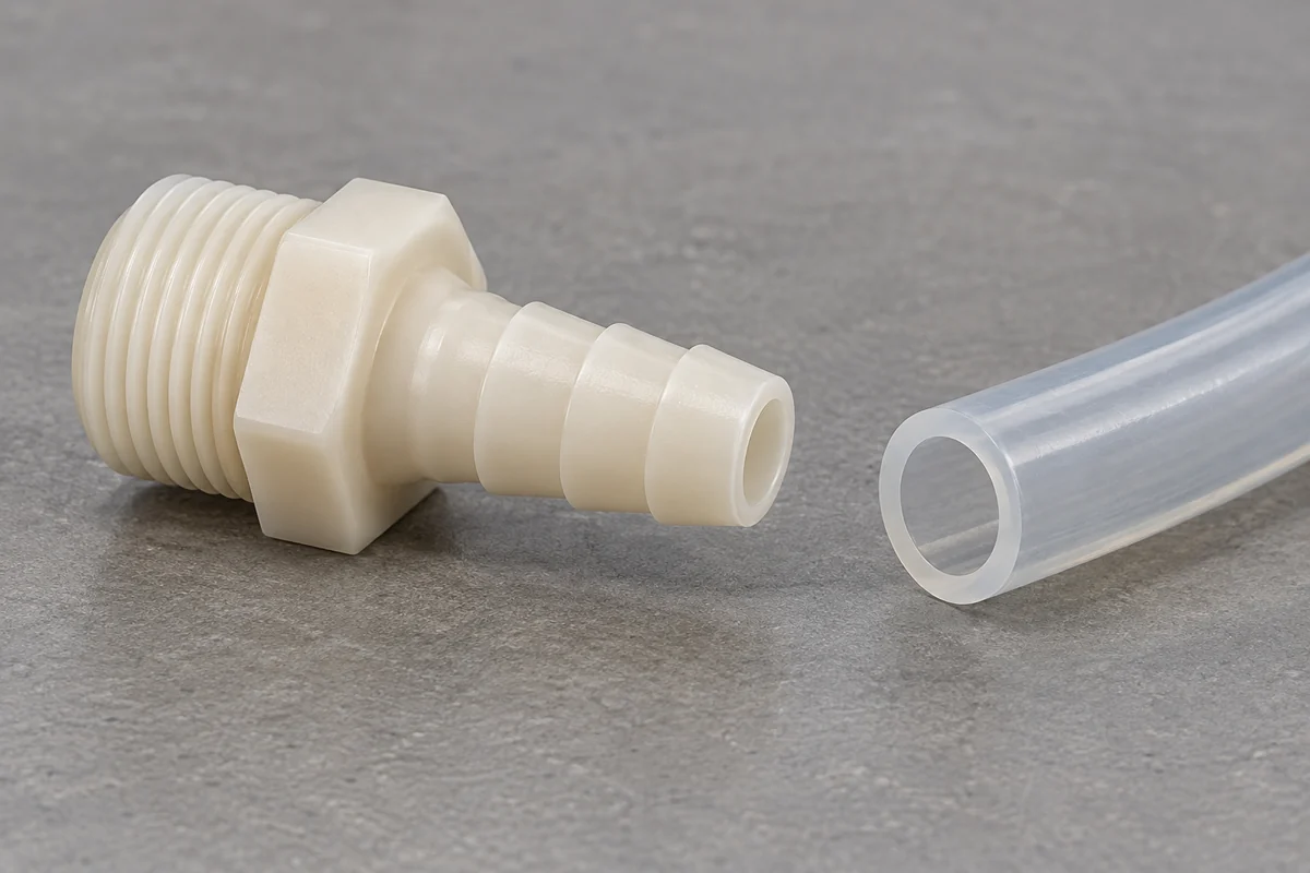
Product design illustrations. Final geometry, materials and acceptance criteria are project-specific.
A hose barb marked for a particular tube size does not necessarily have that same outside diameter. The tube's free inside diameter and the fitting's retaining profile describe different surfaces. Confusing them can create an underspecified drawing or an assembly that is unexpectedly difficult to make. Begin with an unambiguous definition of each dimension and the condition in which it is measured.
The practical question is not simply how much larger the barb should be. The tube must pass over the leading profile, seat to the intended depth and remain suitable for its service environment. Interference influences that behavior, but so do wall thickness, material response, surface condition and assembly method. There is no single oversize value that is appropriate for every flexible tube.
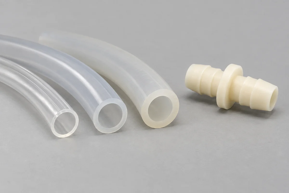
Keep tube ID, tube OD and barb diameter separate
Identify the tube's inside diameter and its tolerance in the free state. Then specify wall thickness or outside diameter as required by the tubing specification. The Nordson MEDICAL fitting catalog identifies barbed connection sizes by tubing ID. That catalog convention helps interpret nominal sizes; it does not establish the geometry or suitability of a new custom fitting.
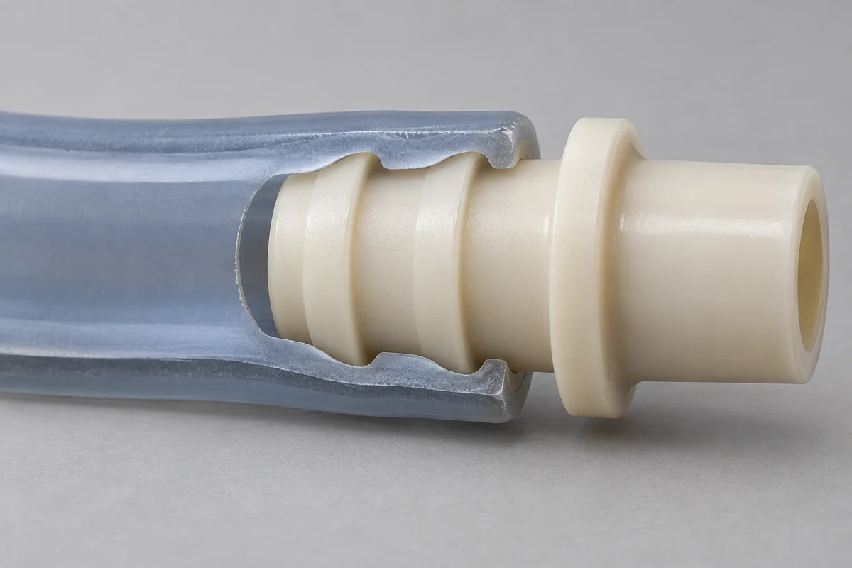
On the fitting drawing, distinguish the lead-in, maximum ridge diameter, valleys, sealing region and shoulder. A measurement across the largest ridge does not describe every point of contact. The inspection method must make clear which feature is being evaluated. Otherwise, different operators can report different dimensions while both believe they have measured the barb diameter.
Review the range of possible interference
A nominal comparison uses the barb diameter minus the tube's free inside diameter. For a tolerance review, also examine the combinations of the largest barb with the smallest tube and the smallest barb with the largest tube. These are geometric bounds, not performance predictions. A positive difference by itself does not show whether insertion, retention or sealing is acceptable.
Consider the condition of each measurement. A freshly molded fitting, a conditioned fitting and a tube after storage or exposure may not represent the same assembly state. Agree when parts are measured and tested. If the intended service changes the tube or fitting, include that state in the validation plan instead of relying exclusively on room-temperature dimensions.
Treat the retaining profile as a shape, not one number
The lead-in and ridge transitions determine how the tube encounters the fitting during assembly. The shoulder and available engagement length determine where it finally sits. A taller ridge may change local deformation without improving the complete connection. Review the profile with the actual tubing rather than assuming that increasing maximum diameter is always the best correction.
Keep the functional surface separate from mold witnesses and gate vestiges. A dimensionally correct ridge can still present an unwanted sharp edge to the tube. Describe acceptable seams and edge condition in the drawing or visual standard. The parting-line and flash review addresses this tooling issue in more detail.
Define insertion depth and assembly aids
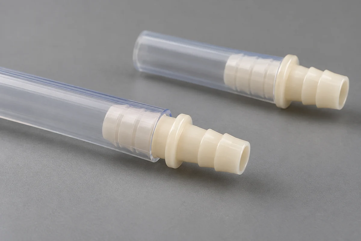
State the intended seated position relative to a visible shoulder or other reference. An assembler needs a practical way to recognize full engagement. If tubing can hide the reference, consider how the assembly will be checked. Do not let the operator choose a different stopping point for each sample simply because the insertion force feels different.
Record whether the connection is assembled dry, with a specified aid or using controlled heating. These conditions can change the comparison and may have compatibility or cleanliness consequences. A method used to make a difficult prototype fit should not silently become an approved production instruction. The responsible team needs to agree both the method and the evidence supporting it.
If a clamp is part of the design, include its exact type, position and installation control. If it is not, document that configuration as well. A clamped result cannot be presented as evidence for an unclamped product. The surrounding installation should also allow the clamp and assembly tools to reach the connection without damaging adjacent features.
Use tests to resolve the fit trade-off
Measure insertion effort and retention using agreed procedures when those characteristics matter to the application. Keep the tube source, sample conditioning, engagement and fixture arrangement traceable. A favorable pull-off result from one combination cannot resolve whether a different tube lot or assembly method will behave the same way.
Retention and leak performance need separate acceptance language. A connection can resist an axial force without meeting a specified leakage criterion, and a brief seal check does not describe resistance to sustained hose loading. Define the actual service-related checks with the system owner. Avoid converting a convenient dimensional fit into a general pressure claim.
When a design change is needed, identify the specific concern first. Excessive insertion effort, incomplete seating, tube damage and low retention are not identical problems. Changing several profile dimensions at once may improve a sample while obscuring the explanation. Record the revision and compare identified specimens under consistent conditions wherever practical.
The final drawing should capture the accepted fitting geometry and reference the controlled tubing and assembly requirements. That connects purchasing, molding and inspection to the same design decision. Without those references, an apparently equivalent tube substitution can reopen the original fit question even though the molded part has not changed.
Review your custom hose connection
Explore our custom injection-molded hose barb fittings and the POM hose-barb retention case study. Send the fitting drawing, exact tubing specification, assembly conditions and acceptance requirements so that the quotation covers a defined part and inspection scope.