
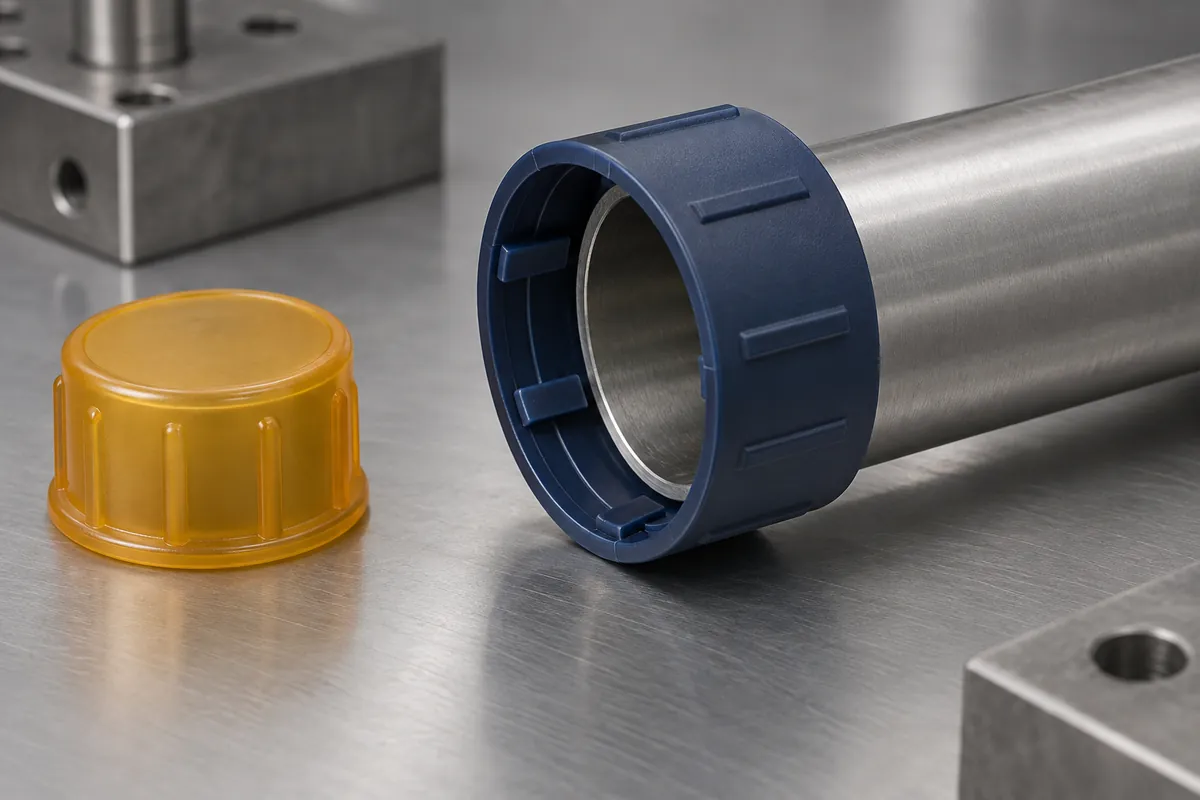
A cap fits one sample tube and feels loose on another, even though both tubes have the same nominal size. The difference may involve actual diameter, roundness, coating, surface condition, engagement length or the cap itself. Selecting a protector from the nominal diameter alone leaves too many of those relationships undefined.
Specify fit as a controlled interface plus an installation and removal requirement. This applies to custom external caps and internal plugs used for temporary protection. A retention check for such a part is not a pressure-seal qualification and should not be described as one.
Product design illustrations. Final geometry, materials and acceptance criteria are project-specific.
Describe the complete mating surface
For an external cap, identify the relevant outside surface, edge geometry and available engagement length. For an internal plug, identify the bore, lead-in, depth and any obstruction. Include the actual tolerance range and surface state rather than relying on a nominal dimension copied from a component name.
Check whether a thread, groove or coating participates in retention. If the protector must avoid contact with a delicate sealing face, show the keep-out area on the drawing. A design that stays in place by gripping the wrong surface can satisfy a casual pull test while damaging the component it was meant to protect.
Review retention and removal as different requirements
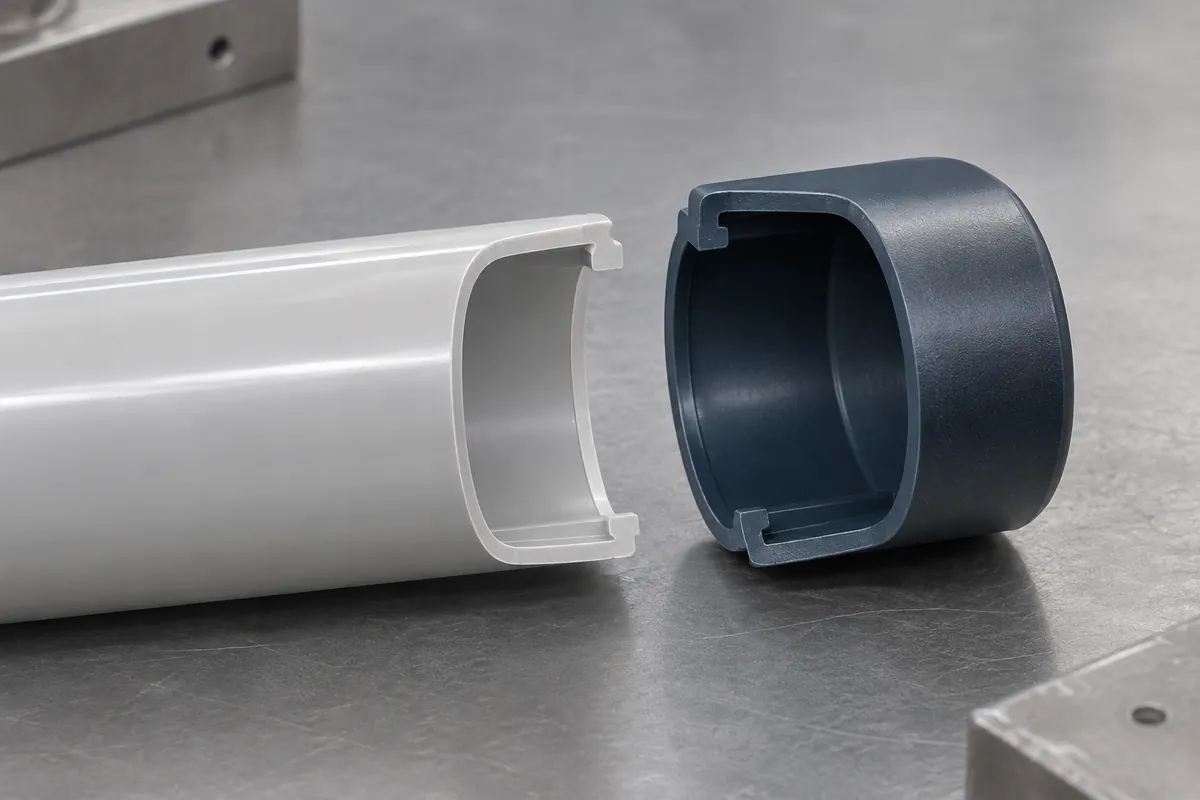
Retention concerns the conditions under which the protector must remain attached. Removal concerns the intended action used to detach it. The two can involve different directions, supports and access. A broad statement that the cap should be both tight and easy to remove does not resolve that distinction.
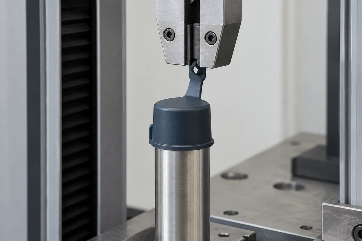
Define the handling sequence. Will vibration, contact with packaging or repeated transfers occur before removal? Does the operator pull a tab, grip the cap wall or use a tool? A tab-assisted removal action may produce a different response from a straight axial pull on the cap body. Both may be relevant, but they should not share an ambiguous test label.
Include the part's condition at the time of use
Record the interval between installation and removal and the relevant environment. Polymer response can change with exposure and time under deformation, so a result immediately after installation may not represent removal at the receiving plant. Do not invent a general retention-life claim from a single fresh sample.
Also identify whether the counterpart carries oil, moisture, coating or another process condition. If the application requires a clean dry surface, the test should use that state. If the real process cannot provide it, the design review should acknowledge the difference rather than testing an ideal condition that production will never achieve.
| Input | Define | Record |
|---|---|---|
| Specimen | Protector revision, grade, cavity and counterpart. | Sample IDs and actual mating condition. |
| Installation | Alignment, seating depth and permitted action. | Any incomplete seating or damage. |
| Exposure | Dwell, temperature and handling sequence. | Actual history before the check. |
| Removal | Grip point, direction, movement and force definition. | Individual result, failure mode and fragments if present. |
Make the fixture reproduce the intended action
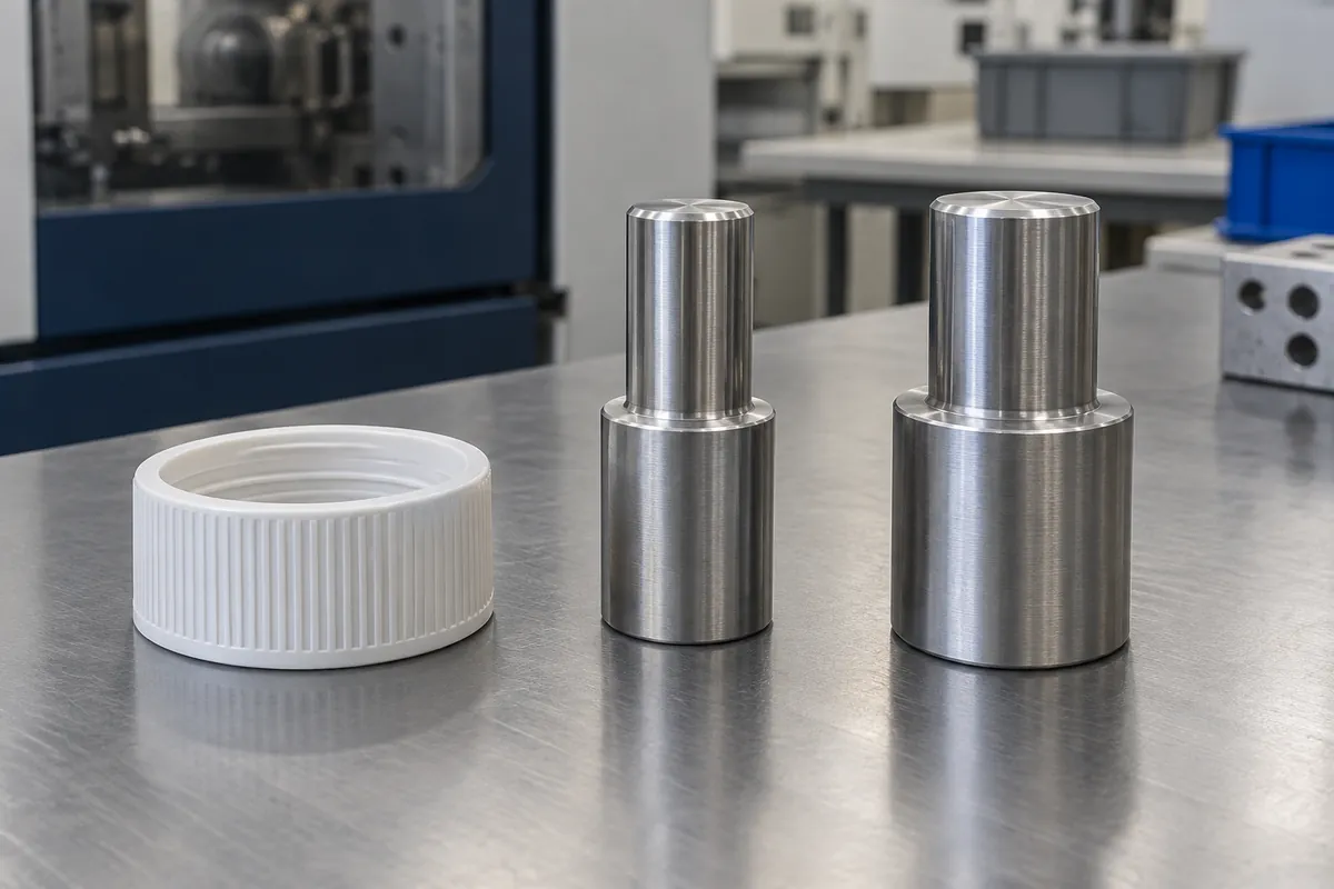
Support the counterpart without introducing an unintended squeeze or constraint. Identify where the protector is gripped and how the load is applied. A clamp that crushes the cap wall can change the contact pressure; a hook in the tab can test a different mechanism from removal by the body.
Instron's fixture guidance illustrates why alignment and controlled force direction matter in mechanical testing. It does not prescribe a standard cap test. Work with the test provider to select a suitable fixture and method for the actual protector and acceptance requirement.
Keep failures informative
If the cap detaches early, the tab tears or material remains on the counterpart, preserve the specimen and its history. Record the observed sequence rather than only the peak force. Different failure modes can require different changes, and a single number may conceal the distinction.
When changing rib geometry or material, compare identified configurations under the same agreed conditions. Do not change the mating mandrel and removal action at the same time unless the new configuration is explicitly the subject of the trial. The removal-tab design guide covers the related geometry review.
Approve the fit range and method with the customer before production. The result should be a bounded statement about the specified protector, counterpart and condition, not a promise that one cap fits every nominally similar tube.
Turn the review into a defined molding scope
Explore our custom injection-molded protective caps and plugs and the related illustrative engineering study. Send the drawing revision, counterpart details, intended use and the decisions still open. Development samples and production approval should have separate, agreed deliverables.