
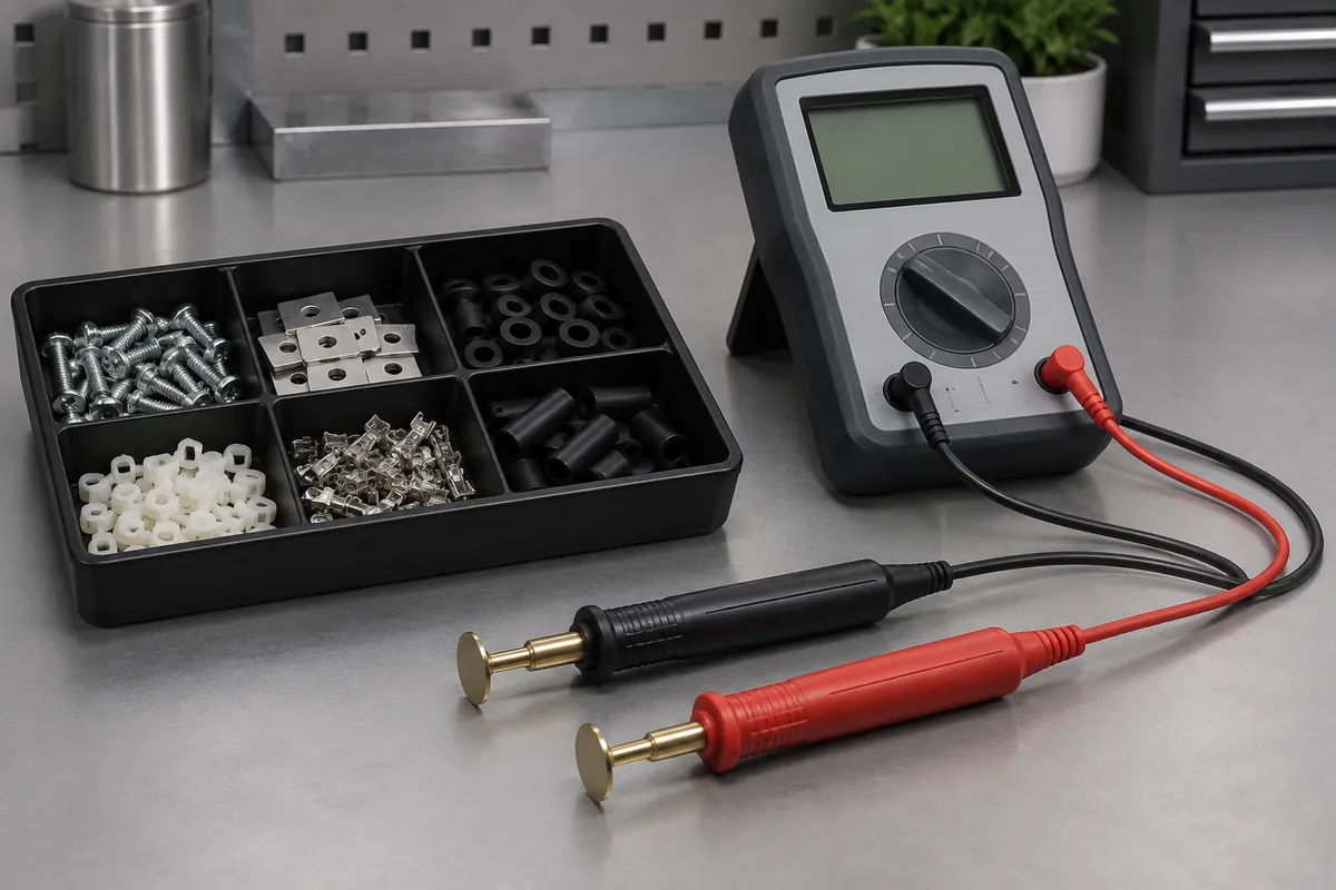
Product design illustrations. Final geometry, materials and acceptance criteria are project-specific.
An ESD-safe tray claim needs a defined protective function and supporting evidence. Black color, conductive filler or a resistance value on a resin data sheet does not by itself qualify a molded carrier for every electronics-handling environment. The finished tray must fit the control program and the sensitivity of the components it carries.
Start by identifying whether the requirement concerns low charging, a discharge path, shielding or a combination. These are not interchangeable properties. The tray's behavior also depends on how it contacts the component and the grounded handling system, so qualify the intended arrangement rather than only a loose material sample.
Separate material description from finished-part evidence
A compound may contain carbon black, fibers or another conductive system. The amount of masterbatch added is not necessarily the amount of active filler in the final mixture. Record the formulation and supplier documentation accurately instead of describing every black PP tray as containing the same conductive loading.
Molding and geometry can affect the measured behavior of a filled material. A flat plaque and a tray with ribs, pockets and limited electrode access are different test articles. Agree how the finished part will be measured and which surfaces or paths are relevant to its use.
The EOS/ESD Association's control-material overview distinguishes packaging functions and relevant methods. In particular, ANSI/ESD S8.1 concerns symbols; it should not be cited as a surface-resistance test or product-performance certification.
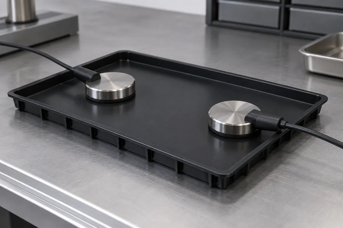
Define the resistance measurement
State whether the requirement is surface, volume, point-to-point or another defined resistance measurement. Include electrode geometry, applied voltage, dwell time and instrument range. A number without its method cannot be reliably compared with a limit taken from a different test configuration.
Record temperature, humidity and conditioning time. Material behavior can change with environment, and a single comfortable-room reading may not represent the controlled qualification condition. Keep the qualification procedure distinct from a simplified incoming or routine production check, with any relationship between them documented.
Identify the sample locations and population. Large trays may contain several relevant surfaces or paths, while cavities or formulation lots may need separate coverage. Report the observed range and sampling scope rather than treating a small test set as full inspection of the shipment.
Do not convert one property into every protection claim
A resistance result can support a particular conductive or dissipative requirement, but it does not automatically establish discharge shielding. Shielding depends on the packaging system and its tested construction. Similarly, a tray may satisfy a resistance window without being acceptable for every charging interaction during loading and separation.
Consider whether the carrier is used only inside a controlled area or during transport outside it. An open tray in a grounded workstation and a packaged shipment have different boundaries. Specify any additional bag, lid or container as part of the protective system where required.
Cleaning and repeated handling may change the surface condition. Establish which exposures the approved tray must withstand and when it should be retested or replaced. A qualification result on a new part does not remove the need to manage worn, contaminated or incorrectly stored carriers.

Plan how the line will distinguish approved carriers from ordinary look-alike trays. A controlled identifier tied to the drawing and compound record is more useful than relying on black color. If replacement trays come from a different cavity set or material lot, retain enough traceability to investigate a changed resistance result without discarding the whole fleet.
Make the purchasing statement precise
Request the exact method, finished-part configuration, conditioning, sample count and recorded results. Separate a supplier declaration from a report that actually covers the delivered construction. Avoid the unsupported phrase certified ESD-safe unless the certification scheme and its scope are identified.
For a reusable molded design, coordinate the electrical review with component contact and cleaning requirements. The useful outcome is a controlled carrier and handling specification, not a broad label that hides which risks have and have not been evaluated.
Discuss the component and its acceptance requirements
Explore our custom component trays and the related project case study. Send the current drawing, mating-part details, operating conditions and required quantities. We can review tooling, molding and inspection as a defined supply scope, with development samples and production approval kept separate.