
Illustrative engineering study · September 24, 2026
Terminal-Carrier Positioning: A Datum and Inspection Study
A terminal pattern can look regular while its position in the assembly remains unclear. Compare the locating references before writing an acceptance report.
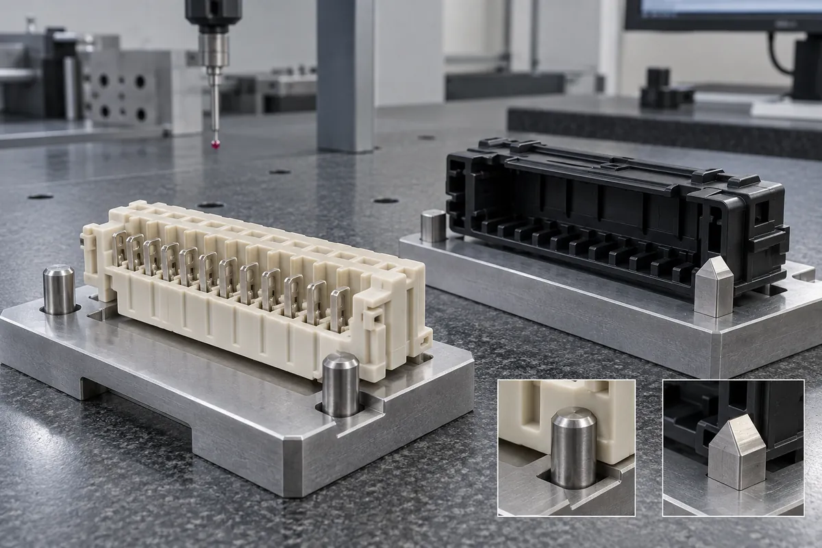
The design question
What actually locates the carrier?
Consider a molded carrier that holds a row of terminals inside an equipment enclosure. The terminals must enter their corresponding receiving features after the carrier is mounted. The part drawing shows the terminal-window pattern, but the relationship between the inspection support and the assembled mounting is still open. There is no approved tolerance or selected resin grade in this example.
The first decision is not which measuring machine to use. It is which surfaces establish the position of the part when it does its job. A fixture resting on a convenient broad wall might support a dimensional check while representing a different condition from the mounting pads used in the actual assembly. Both observations can be useful, but they answer different questions.
Keep the terminal arrangement, required mating action and counterpart revision common to the comparison. If a proposed locating concept also changes the enclosure or terminal position, record that as a design change. Otherwise a successful fit could be attributed to the carrier when the counterpart was the item that changed.
Concept comparison
Broad walls or defined mounting interfaces?
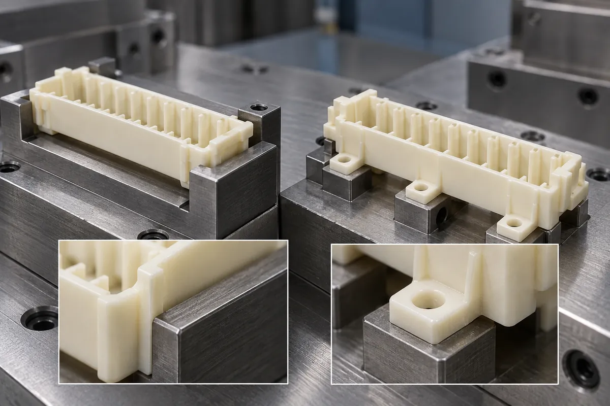
Concept A supports and locates the carrier against long molded walls. Concept B uses deliberately identified mounting pads, a side reference and an end stop. The diagram is a discussion aid: it does not prescribe a datum system, number of contacts or drawing notation for an actual component.
For A, the review asks how wall form, flash restrictions and applied restraint affect the seating condition. For B, it asks whether the proposed interfaces are present in the assembly, can be molded and inspected reliably, and remain accessible after terminal installation. Neither concept is automatically more accurate.
A broad-wall fixture may be convenient when those walls genuinely locate the assembly. Defined pads may be useful when they correspond to controlled mounting interfaces. The important distinction is functional relevance, not whether a fixture looks more sophisticated. Document the restraint and loading state before comparing measurements.
Proposed inspection
Separate local spacing from pattern location.
Adjacent terminal spacing and overall pattern position are different characteristics. A sequence of apparently consistent neighboring windows does not, by itself, demonstrate that the pattern is correctly positioned relative to the mounting references. Agree which features require individual values and which assembly conditions need a functional check.
Measure the carrier in the agreed specimen state. An empty plastic body, a body after terminal installation and an exposed assembly can have different constraints and histories. Keep their records distinguishable. If reflow or another thermal step is relevant, define its actual profile and the required post-exposure check rather than assigning a resin-family temperature guarantee.
| Question | Method inputs to approve | Evidence to preserve |
|---|---|---|
| Local geometry | Window features, feature extraction, specimen condition and drawing limits. | Individual results linked to part, cavity and drawing revision. |
| Pattern location | Approved reference features, fixture contacts and restraint. | Pattern-to-reference results and the actual measurement setup. |
| Mating function | Controlled counterpart, installation state, insertion action and acceptance. | Functional observations, gauge identity and any damage or interference. |
| Exposure effects | Applicable process or environment and before/after specimen state. | Paired records with exposure identity; no inferred life or rating. |
A functional gauge can reveal a combined interface problem while not explaining which feature caused it. Conversely, a dimension report might not reproduce the intended mating action. The functional-gauge comparison treats these as complementary methods with separate acceptance purposes.
Cavity-aware evidence
Do not average away a location problem.
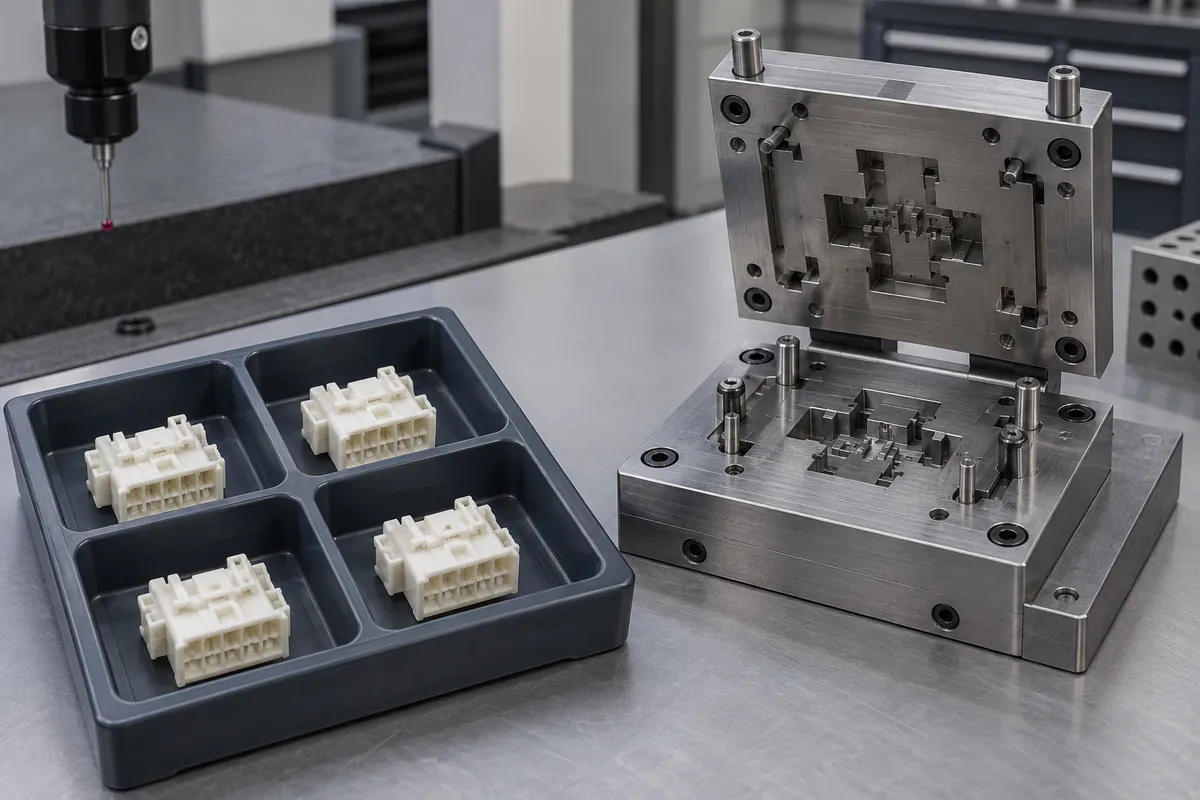
A multi-cavity trial should preserve each sample's origin. If an overall average combines different cavity populations, it can conceal a repeatable difference that matters at assembly. Agree the sampling plan for the actual tool and stage of development; no universal sample quantity is invented here.
The record should connect sample ID, cavity ID, molding run, exact resin, drawing revision and inspection method. Preserve invalid measurements with their reason and disposition. If a fixture is adjusted between groups, record the adjustment rather than treating every result as if the setup were unchanged.
ZEISS's calibration guidance describes the role of calibration in measurement equipment. For this study, equipment calibration is only one part of a proposed method: part location, feature definition and the required decision must still be established. No specific measuring equipment or accredited service is promised by FECISION here.
Decision and next step
Release a method before announcing an improvement.
The study's deliverable is a controlled comparison of locating concepts and a proposed evidence package. A real project could retain broad-wall location, develop the mounting-pad concept or revise the counterpart interface. That decision requires actual drawings, feasibility review and the agreed measurements or functional checks.
Before tooling release, assign ownership for the datum definition, terminal-installation requirements, functional gauge and final assembly acceptance. Resolve open assumptions in writing. After trials, assess the identified results against the pre-agreed criteria and retain any approved deviations. There is no demonstrated improvement in pin position, yield or electrical performance in this illustrative study.
Apply the review to your part
Turn your drawing into a defined review.
Send the carrier, terminal and mounting drawings together, with the intended inspection state and the interfaces that cannot change.
Explore our custom molded connector insulators and terminal carriers or the broader injection molding service.