
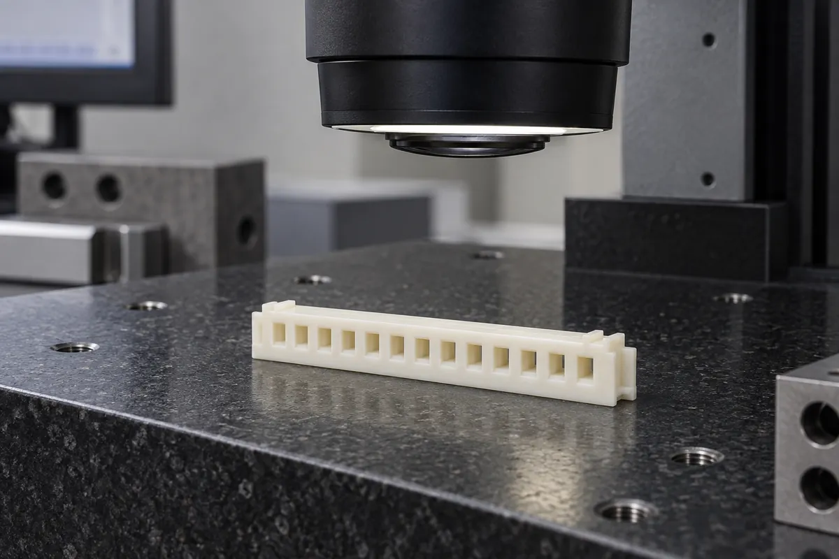
Every adjacent terminal window can appear evenly spaced while the complete pattern sits in the wrong place relative to the mounting face. Conversely, one unusual gap can disappear inside an average calculated over a long row. These are different inspection problems, even though both may be described informally as a pin-pitch issue.
For an empty molded carrier, inspect the plastic features that locate the terminals and state how those measurements relate to the final assembly. Do not report metal pin position when the delivered part contains no pins. The acceptance drawing should separate aperture size, local spacing, pattern location and the surfaces that establish the measurement reference.
Product design illustrations. Final geometry, materials and acceptance criteria are project-specific.
Begin with the assembly reference
Ask how the carrier is located in its mating housing or assembly fixture. A flat mounting face, a side feature and an end stop may each constrain a different direction. The drawing's datum system must describe the intended reference consistently; an inspector should not create a convenient substitute simply because another face is easier to reach.
Distinguish the actual molded datum feature from the ideal reference constructed during measurement. A visibly flat-looking side is not automatically the right primary reference, and a flexible wall may respond to contact force. Document the fixture, the support points and any restraint. If the drawing requires a restrained condition, the restraint needs a defined method, not a bench clamp tightened by feel.
Three measurements answer three questions
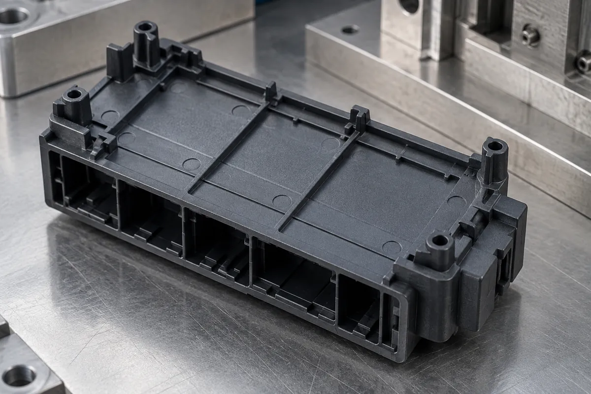
Adjacent pitch compares neighboring feature locations. Overall span compares selected locations across the array. Datum-based position relates the pattern to the part's locating features. Report the quantities required by the drawing rather than selecting whichever produces the most attractive summary. They are not interchangeable checks.
Consider a purely illustrative row of six aperture centers at coordinates x1 through x6. Five equal-looking local spacings do not, by themselves, establish where x1 lies relative to the mounting datum. Likewise, dividing the total span by five only gives average spacing. It can conceal compensating local deviations. This example defines relationships; it supplies no dimensions, tolerance or measured result.
| Characteristic | Question answered | Record to preserve |
|---|---|---|
| Aperture size and form | Will the specified terminal interface have the required geometry? | Feature ID, measurement definition and actual result. |
| Adjacent spacing | How are neighboring locating features separated? | The two feature IDs and the individual spacing result. |
| Pattern location | Where is the array relative to the assembly reference? | Datum setup, alignment method and the required positional result. |
| Overall span | Does the array meet its specified end-to-end relationship? | Selected endpoints and the span definition. |
Make the measurement method reproducible
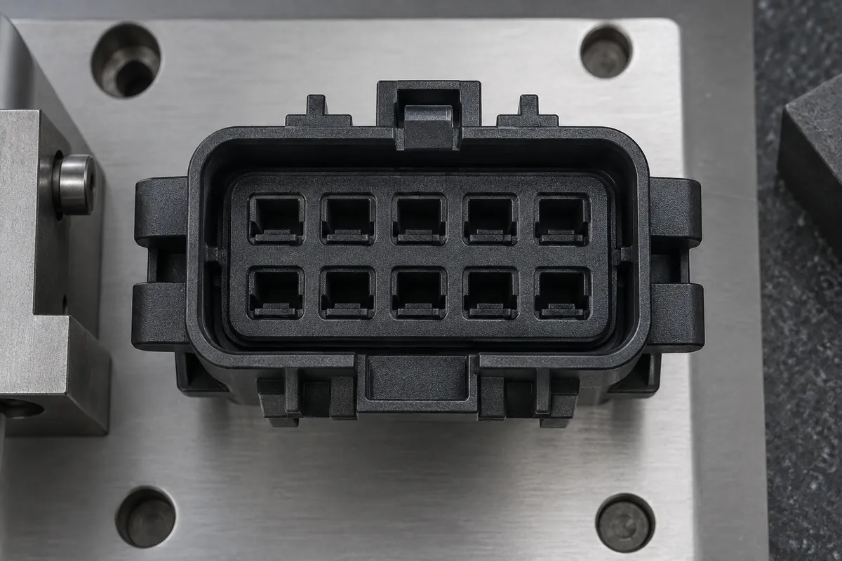
Define how the measuring system finds a window's location. An optical edge measurement, a probe touching accessible walls and a fitted geometric element may respond differently to draft, radii or flash. Record the section or height being evaluated and the software method used. Changing that method mid-comparison can change the reported result without any change to the part.
The equipment also needs appropriate verification. ZEISS explains the role of equipment calibration in its metrology calibration guidance. Calibration is necessary context, but it does not select the correct datum alignment or prove that a particular thin feature can be measured without distortion. Evaluate suitability for the actual characteristic.
Agree how repeated measurements and different operators will be compared before resolving a borderline result. A measurement system investigation should not be hidden by rounding more aggressively or changing alignment until a part passes. Keep the original result, the revised method and the reason for any change together in the record.
Specify when and in what condition the part is checked
The drawing and inspection plan should name the relevant part state: as molded after an agreed stabilization period, conditioned, assembled, or after a defined thermal exposure. Those states should not be mixed in one trend without identification. If the requirement concerns post-reflow fit, an incoming dimensional report cannot automatically close it.
Keep material grade, cavity, sample ID and conditioning history attached to each result. For a multi-cavity tool, pooled averages may hide a pattern specific to one cavity. Start with individual records and only then calculate the summaries appropriate to the agreed plan. See cavity-level traceability for the practical sample-to-record link.
Use assembly checks as additional evidence
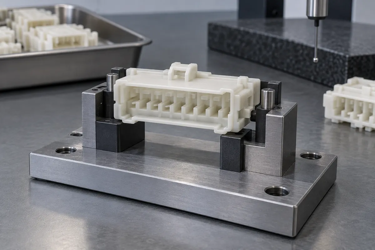
A mating gauge can quickly reveal an interface problem, but its result has a defined scope. Passing one fixture does not automatically establish every drawing characteristic, and a failed fit does not identify the root cause by itself. Pair the result with the relevant measurements and the gauge's own controlled revision.
Finally, keep tool dimensions and molded-part measurements separate. A precise cavity inspection documents the tool; it does not prove the terminal pattern on every molded carrier. Approval should name the actual delivered part, its condition and the evidence required to release it. Our gauge-versus-dimensions guide explains how the two forms of evidence can work together.
Turn the review into a defined molding scope
Explore our custom molded connector insulators and terminal carriers and the related illustrative engineering study. Send the drawing revision, counterpart details, intended use and the decisions still open. Development samples and production approval should have separate, agreed deliverables.