
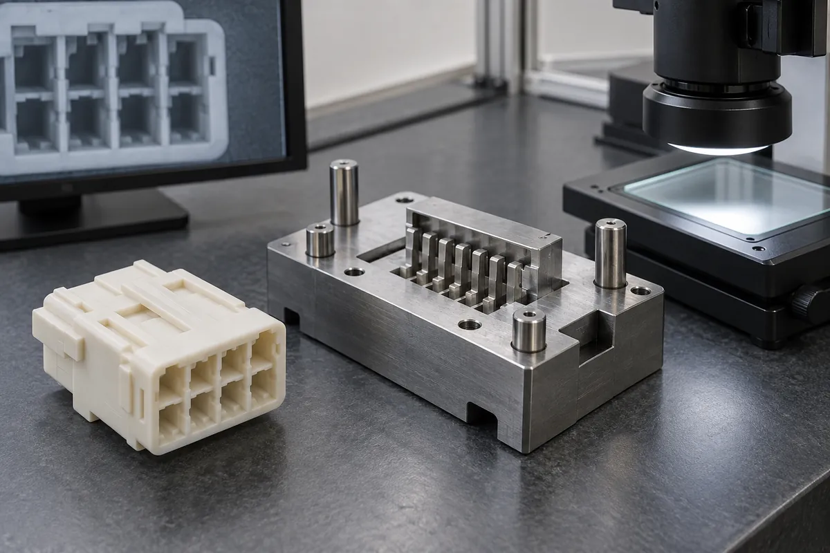
The sample fits the checking fixture, yet one of its drawing dimensions is outside the specified limit. Should the part pass? The answer cannot be decided by whichever result is more convenient. It depends on the approved acceptance requirements, what the fixture checks and whether a documented concession or design change has been authorized.
A functional gauge and a dimensional report provide different evidence. A well-defined gauge can test a combined interface efficiently; individual measurements can identify the size or location behind an assembly problem. Used together, they make connector-part approval clearer. Used as substitutes without agreement, they create disputes.
Product design illustrations. Final geometry, materials and acceptance criteria are project-specific.
Write down the gauge's intended question
Is the gauge checking terminal entry, combined alignment, latch engagement or the envelope of a mating part? Identify the exact function before designing the fixture. A smooth pin entering an opening is not necessarily a test of terminal retention, and a housing sliding into a nest is not evidence of electrical performance.
Describe the sequence, direction, permitted force, support and stop condition. “Must fit” leaves the operator to decide whether rocking, pushing harder or changing the angle is allowed. If the test can damage the part or wear the mating features, define whether the specimen can be reused and how many operations are permitted.
Keep drawing compliance visible
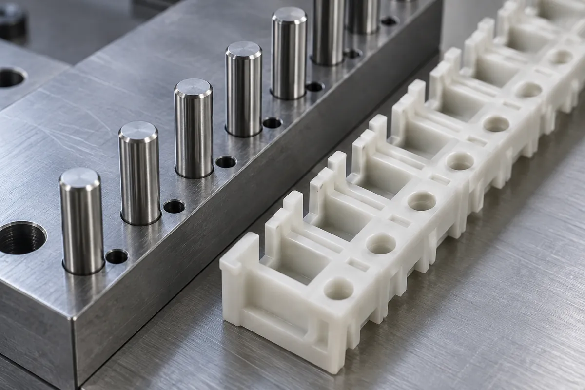
List which characteristics the gauge evaluates and which still require individual measurement. Some features may remain completely outside its reach, such as an inaccessible wall, a sealing land or a locating face on the opposite side. A combined fit check should not silently remove those drawing requirements.
Where geometric tolerancing defines the intended functional boundary, have the design and quality teams review the gauge against the applicable drawing rules. Do not infer a valid functional gauge merely by reproducing nominal CAD. The gauge's own tolerances, wear allowance and verification method are part of its specification, not details to settle after first use.
For the separate dimensional report, preserve feature IDs and the datum setup. The carrier inspection guide distinguishes local pitch from pattern location. That distinction can explain why a combined interface fails even when selected local measurements look acceptable.
| Evidence | Useful for | Does not automatically establish |
|---|---|---|
| Controlled mating gauge | A specified combined interface under a defined action. | All dimensions, electrical behavior or sealing performance. |
| Individual measurement | Size, form or location of named characteristics. | The behavior of the complete assembly under service conditions. |
| Approved counterpart assembly | Assembly behavior using identified mating parts. | Performance across all counterpart tolerance combinations. |
| Engineering disposition | A documented decision on a stated deviation. | A permanent change to the drawing unless expressly released. |
Control the gauge like a production item
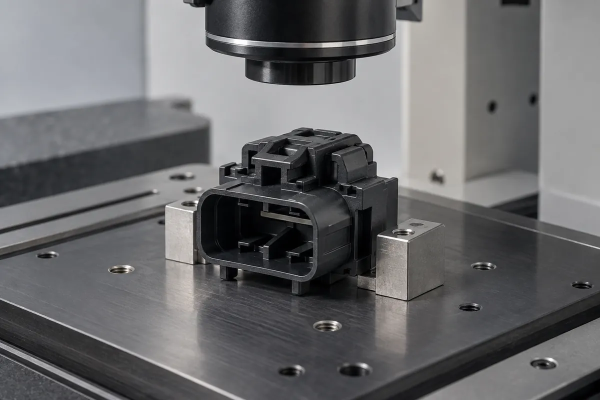
Give the fixture an identifier, drawing revision, verification status and storage location. Record which surfaces wear and which accidental changes could affect the result. A polished replacement pin or a repaired locating stop can change the test; it should not enter service as an undocumented workshop adjustment.
ZEISS's calibration guidance describes the importance of equipment verification. The practical purchasing task is to agree what verification evidence your gauge requires, who provides it and when re-verification is triggered. Do not assume that owning a precision instrument establishes the fitness of every fixture used with it.
Repeatability matters as well. Have the method evaluated with the expected operators and sample range before it becomes a release gate. A fixture that gives different answers after a small change in loading technique needs a method or design review, not a more forceful instruction to the operator.
Investigate disagreements without deleting evidence
When a sample passes the gauge but fails a dimension, retain both results and confirm that they refer to the same specimen and condition. Check drawing revisions, gauge status, alignment and the characteristic definitions. If the dimension is truly out of tolerance, an engineering decision is needed; the gauge result alone does not rewrite the requirement.
When it passes dimensions but fails the gauge, investigate characteristics not captured by the selected measurements and the gauge itself. A counterpart revision, support condition or combined tolerance relationship may explain the disagreement. Record the investigation rather than repeatedly selecting new samples until the discrepancy disappears.
Agree the release package
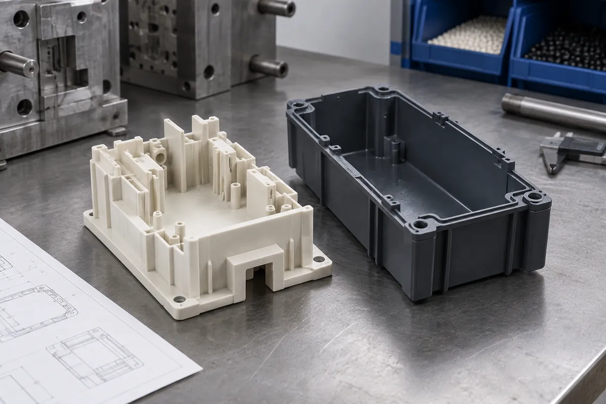
For trial approval, connect the drawing report, gauge result, cavity ID and any assembly observations to one specimen register. Note destructive checks and retained samples. A concise combined register is more useful than separate files whose sample numbers cannot be reconciled.
Finally, name the decision owner and the hold point. A supplier can provide inspection evidence while the customer's assembly team retains final approval authority. Put that division into the RFQ so that a completed report is not mistaken for permission to ship production.
Turn the review into a defined molding scope
Explore our custom molded connector insulators and terminal carriers and the related illustrative engineering study. Send the drawing revision, counterpart details, intended use and the decisions still open. Development samples and production approval should have separate, agreed deliverables.