
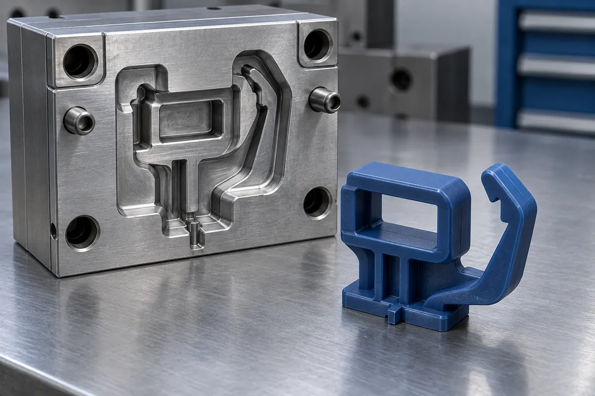
The easiest place to remove a gate vestige is not necessarily the best place to introduce material into a load-bearing clip. A gate decision can change the filling path around openings, the appearance of contact surfaces and the conditions near a flexible arm. Yet an RFQ may specify only that the finished part should have no visible gate mark.
Review the gate proposal against a functional map of the clip. Mark the beam root, hook contact, assembly clearances and cosmetic zones before comparing candidates. This article narrows the question to clip performance; the broader weld-line guide remains the reference for general defect discussion.
All images in this article are newly AI-generated illustrations of engineering concepts, not photographs of a customer project or evidence of completed testing.
First Mark Where the Part Must Work
On a hypothetical panel retainer, the broad base locates the part, a window interrupts the base and a cantilever arm carries the latch. Highlight the regions where bending, mating contact and inspection are important. This map does not calculate stress, but it tells the tool designer which regions need more than a cosmetic review.
Add the surfaces where a gate vestige or trimming operation would interfere with assembly. A location away from the flexible root can still be unacceptable if the vestige contacts the mating panel. Likewise, a hidden surface is not automatically a suitable location if access to trim and inspect it is poor.
Ask the supplier to show the proposed gate location, type and relevant runner arrangement on the same revision of the part. A sentence saying “optimize the gate” is not enough to compare two quotations. The underlying geometry and material assumptions need to be visible.
Compare Two Locations Without Pretending to Have a Simulation
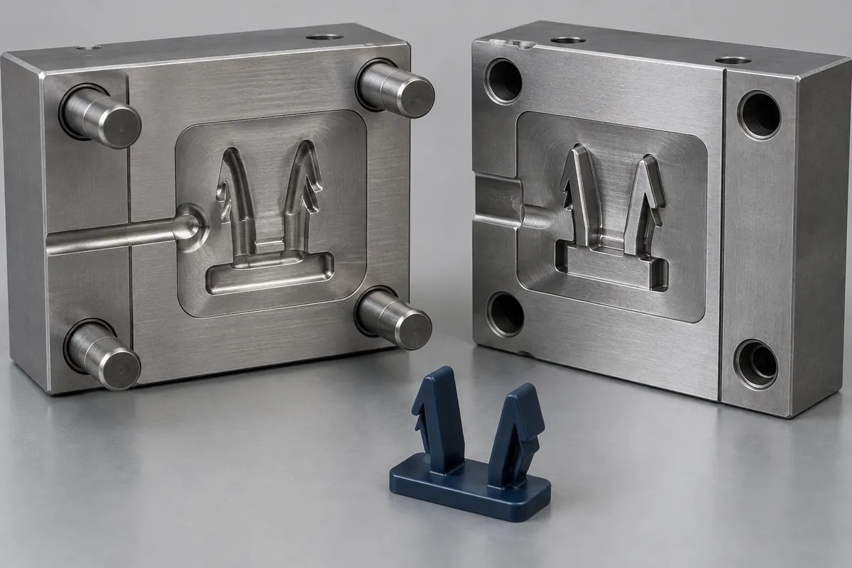
Concept A introduces material from one side of the base, beside the window. Concept B places it on a different base edge. Both must fill the same clip. In either case, flow around an opening may separate and meet again; the design question is where this happens relative to the functional regions.
The sketch below maps questions, not predicted flow-front results. The arrows identify candidate entry directions only. No weld-line location, pressure, temperature, fiber orientation or mechanical result has been calculated. An actual simulation needs the proposed geometry, material and processing inputs.
BASF's injection-location comparison shows why different filling concepts can change several outcomes at once. For a clip review, compare the relevant outputs together rather than selecting a gate solely because one displayed metric improves. A proposal that benefits one interface may create an issue elsewhere.
Separate Appearance, Flow Evidence and Mechanical Evidence
A visible line can trigger an investigation, but appearance alone does not quantify the clip's load capacity. Conversely, a smooth-looking surface is not proof that every critical region has the required properties. Keep cosmetic inspection and functional validation as separate acceptance questions.
Where simulation is in scope, retain its assumptions and version with the result. Where trial molding is used to study filling, identify the samples and process conditions. A short-shot sequence can help investigate a filling pattern, but it is not itself a service-load test.
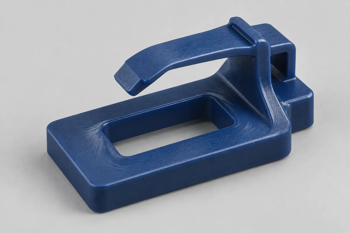
For the mechanical question, agree a test that represents the clip's required function and support. Our cycle-testing guide explains why the mating part and release action belong in the method. If a sustained load is relevant, add an appropriate retention exposure rather than relying on repeated opening alone.
Make the Tooling Tradeoffs Explicit
Each gate candidate needs a practical review of access, vestige control, trimming, inspection and the surrounding tool construction. Ask which regions are expected to need trial confirmation and whether the tooling proposal allows the agreed development changes. Do not assume every gate relocation is a minor adjustment after steel is cut.
Also ask which drawing or process changes would reopen validation. If a late gate move changes the molded configuration, the earlier sample evidence may no longer describe the release candidate. Keep the approved gate arrangement connected to the part and process records, rather than treating it as a private tooling detail.
Close the Decision with an Evidence Plan
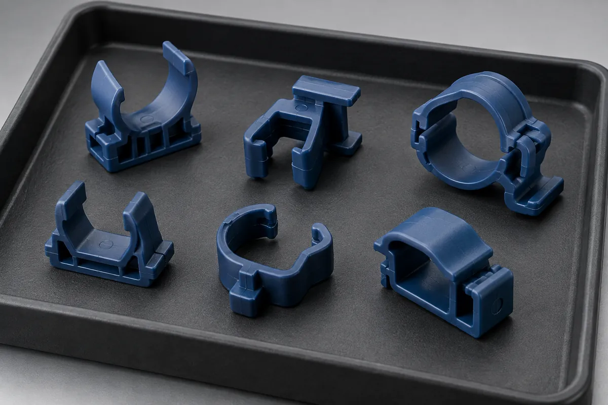
The useful outcome is a selected concept, a reason for the selection and a list of checks still needed. The reason may include functional risk, vestige access and tooling practicality. It should not claim that a weld line has been eliminated or that retention has improved unless the relevant evidence exists.
Keep the material decision connected to this review, especially when comparing unfilled and reinforced grades for flexible clips. A gate and resin proposal should describe one identifiable manufacturing configuration, not two independent promises that have never been assessed together.
For custom injection-molded clips and retainers, include the critical functional zones and any gate restrictions with your CAD. Request a quote with a gate and validation review. Confirm whether simulation, trial investigations and mechanical tests are included before comparing the quoted scope.