
Illustrative engineering study · September 24, 2026
Releasable Snap-Fit Clip: Two Concepts and a Validation Plan
Compare a compact latch with an extended flexible region, then define the evidence needed to choose between them.
The design question
A removable cover needs more than a positive click.
A hypothetical equipment cover must engage a receiving window and remain removable for service. The mating envelope and available access are constrained, but the length of the flexible region is still open to review. There is no approved resin grade, force limit or cycle requirement in this example.
The study therefore compares questions and proposed validation, not measured outcomes. Before a real project proceeds, the owner must supply the actual drawings, environment and acceptance requirements. A visually plausible latch is only the beginning of that process.
Keep the common requirement visible
Use the same required engagement, receiving-window interface, surrounding assembly and intended service action. If a concept changes one of these, record it as a new requirement or approved design revision.
Identify the open variables
Flexible length, section, root transition, material grade and tooling approach remain design inputs. Changing several together creates a new configuration, not evidence that one isolated feature caused an improvement.
Concept comparison
Compact arm or a longer flexible region?
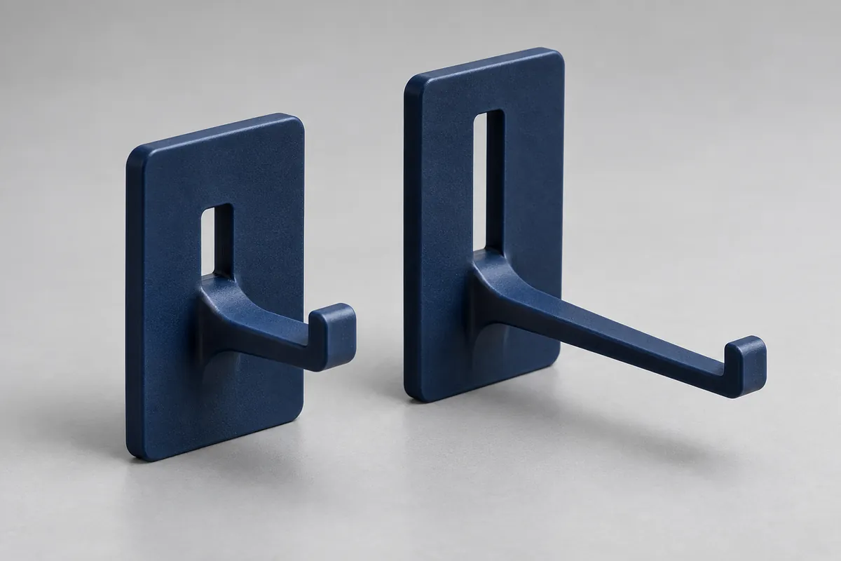
Concept A uses a short straight cantilever region. Concept B extends a relief slot to create more available flexible length within the cover. Neither sketch sets manufacturing dimensions or an allowable strain. The purpose is to expose a tradeoff that can be discussed before tooling.
BASF's snap-fit design reference identifies geometry and material strain as inputs to an engineering calculation. For this study, no such calculation has been completed. A real review must check the actual boundary conditions and whether a simplified beam assumption represents the surrounding wall.
| Area | Concept A | Concept B |
|---|---|---|
| Packaging | Shorter flexible region occupies less wall length in this concept. | Longer relief slot uses more of the cover wall; check surrounding features and openings. |
| Assembly response | Review the displacement demanded by the same mating interface and tolerance combinations. | Review whether the changed flexible region is suitable for the same required engagement; do not assume a force result. |
| Release access | Confirm access to the tab and clearance throughout the intended action. | Confirm that the longer slot and arm do not obstruct access or introduce unwanted contact. |
| Tooling and filling | Review gate, root filling, undercut and ejection for this geometry. | Repeat that review for the revised geometry; the previous tooling conclusion is not automatically transferable. |
| Evidence required | Identified molded samples, defined mating part and approved inspection/test method. | Equivalent functional requirements and controlled sample history for a meaningful comparison. |
A longer slot may help create the intended flexible region while affecting appearance, access or environmental separation. A compact arm preserves space but still needs its assembly displacement and material response checked. These are reasons to investigate each concept, not reasons to announce a winner.
Proposed validation
Define a repeatable insertion and release sequence.
Agree the fixture and the mating part before preparing comparison samples. The fixture should represent the intended support or clearly state that it is a screening substitute. A clamp close to the root can change the flexible boundary, so it must not be an undocumented convenience.
Record the action used to release the latch. Depressing a tab and then withdrawing the cover is a different test from pulling on an untouched latch. The acceptance plan should distinguish these actions and identify any accidental-withdrawal requirement separately.
| Evaluation | Method inputs to agree | Evidence to retain |
|---|---|---|
| Configuration | Drawing revisions, exact resin, molding history, sample IDs, counterpart and conditioning. | Keep each concept and manufacturing condition identifiable; no mixed unlabeled sample groups. |
| Insertion | Alignment, fixture support, movement, speed, travel and the force definition. | Individual observations and relevant force/travel data; confirm full engagement, not just completion of travel. |
| Deliberate release | Tab actuation, access, removal path and counterpart replacement policy. | Release and withdrawal observations; separate these from an untouched-latch pull test. |
| Repeated operation | Cycle sequence, dwell, count, observation intervals and stop/failure criteria. | Individual cycle history, first observed change, damage images and any invalid-run disposition. |
| Sustained retention | Separate load/displacement boundary, environment, exposure and measurement state. | Required retained function after the agreed exposure; no extrapolated life claim without a justified method. |
Sample numbers, observation intervals, operating speeds and acceptance limits are intentionally not invented here. They need to be selected for the actual requirement and method. A development comparison can proceed with a clearly labeled exploratory purpose, but it should not be renamed production qualification afterward.
If a specimen stops engaging, cracks or changes beyond an agreed limit, preserve its history and disposition. Do not omit it because another specimen completed the run. The cycle-testing guide explains the proposed record structure in more detail.
Manufacturing review
The selected concept still needs a molding plan.
Review the exact candidate resin, the gate and filling concept and the undercut release route together. A latch that flexes in service is not automatically suitable for forced release over mold steel.
Use representative molded samples for the release decision where required. A prototype can expose access or interface problems, but its manufacturing history must stay visible. Do not describe a printed fit check as validation of a molded resin and gate configuration.
Apply the review to your part
Discuss a custom clip with its mating assembly.
Send CAD, counterpart drawings, release access, exposure, quantities and the requirements that must be preserved. Explore our custom injection-molded clips and retainers application page, or start with the cantilever design review.