
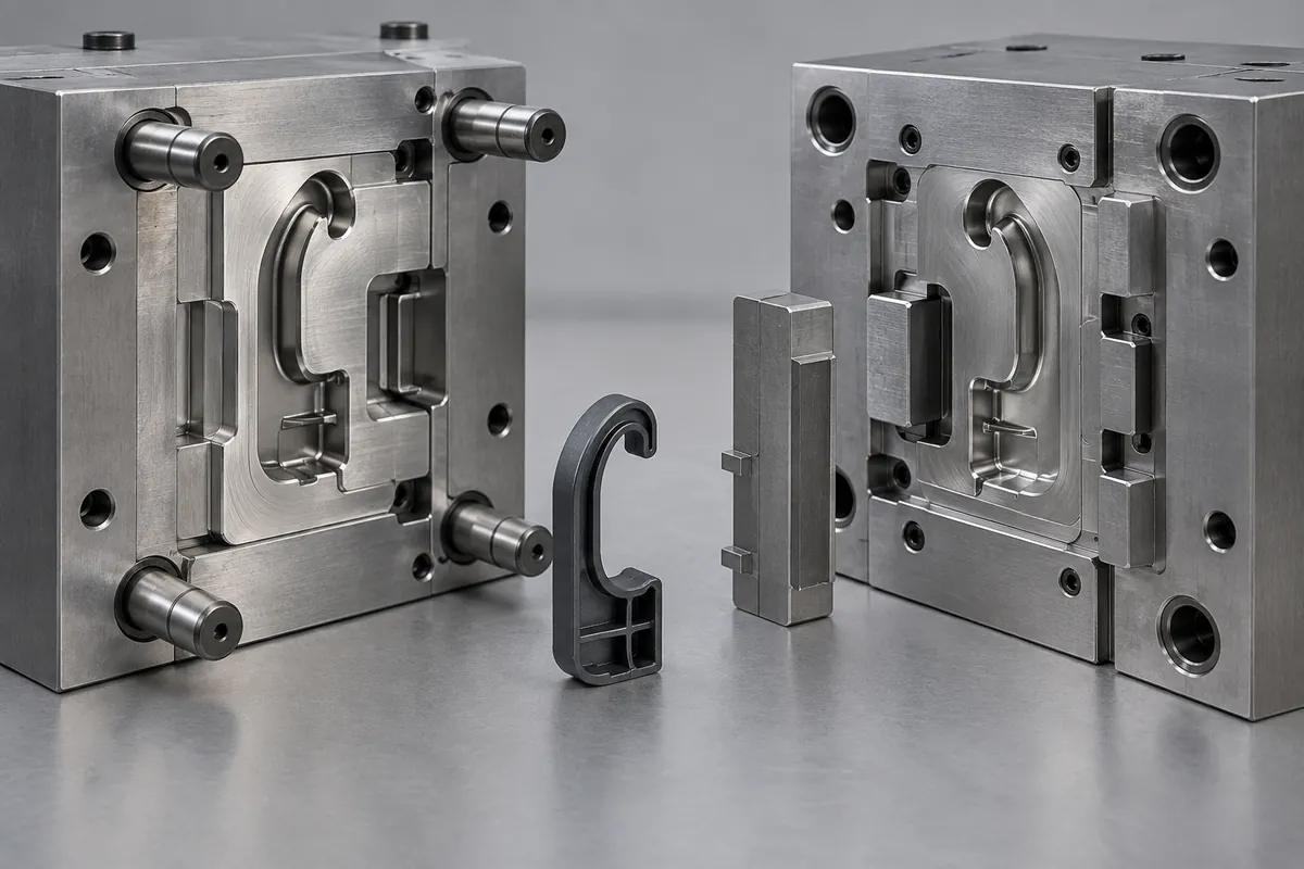
A clip can flex during assembly and still be unsuitable for forced release from its mold. The contact direction, available clearance and material condition during ejection can differ from those in service. Treating “it is flexible” as permission to pull it over trapped steel skips the important part of the tooling review.
Compare the actual ejection path with a side-core withdrawal path before approving either route. Flex-release is a candidate only when the geometry and material can accommodate the proposed movement without unacceptable damage or permanent change. A side action is a tooling alternative, not an automatic guarantee of a trouble-free part.
All images in this article are newly AI-generated illustrations of engineering concepts, not photographs of a customer project or evidence of completed testing.
Locate the Trapped Steel in a Section
Use a section through the hook and the relevant mold-opening direction. Identify the steel that occupies the space behind the retention feature. Then draw the sequence that must occur before the molded part is free. An exterior view of the finished clip rarely makes this interference obvious.
For a conceptual panel clip, the functional hook may be fixed by the receiving-panel interface. Keep that interface unchanged while initially comparing tooling routes. If a proposal requires a shallower hook, a new radius or a changed parting surface, mark it as a design change rather than calling it the same part with a cheaper mold.
Our general undercut guide explains the broader tooling options. Here the narrower question is whether this clip can be released by controlled flexing or whether the obstructing steel needs to move first.
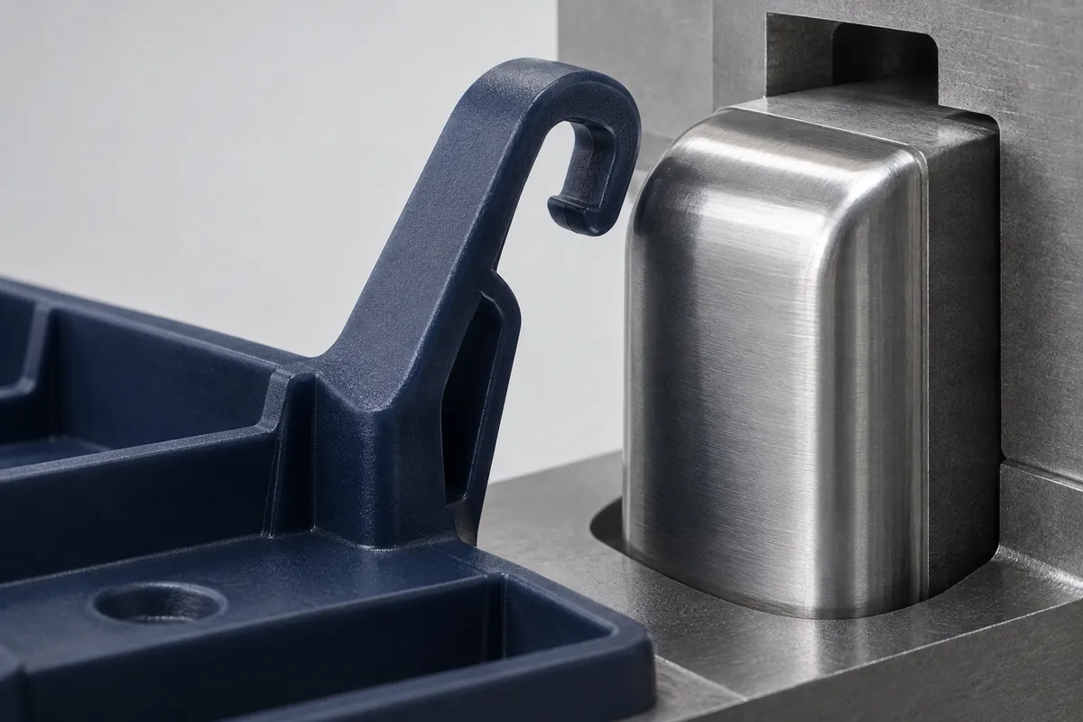
Flexing Needs a Suitable Contact Path and Room to Move
Protolabs' bumpoff design guidance describes the importance of a suitable ramp or radius and enough freedom for the plastic to deform. A sharp trapping hook is not equivalent to that geometry. Do not apply a generic allowable undercut percentage to an unreviewed clip.
Review where the arm moves as the part is ejected. Nearby ribs, adjacent cavities, the opposite mold half or the remaining core can prevent the movement that seems possible in an isolated CAD model. State when the constraining steel has cleared and how the part is supported during the event.
The review also needs the exact resin grade and the proposed molding condition. A successful room-temperature hand flex is not evidence of acceptable ejection. Ask what trial observations will be used to check the hook edge, beam root, free position and later assembly function.
A Side Action Moves the Steel, but Adds Its Own Interfaces
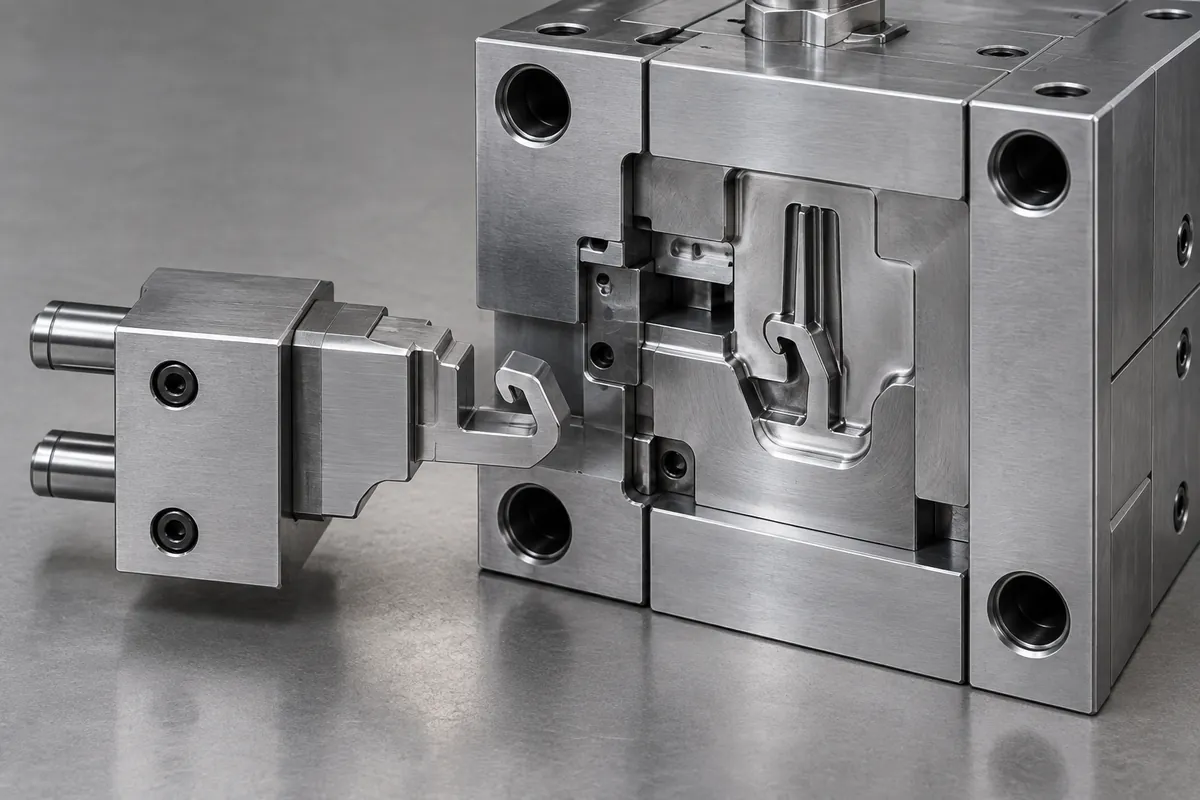
In the alternative concept, a side core withdraws from behind the hook before the main ejection step. Show its travel direction and the clearance needed around the tool. Check the sequence with the rest of the mold rather than assuming a slide can be added wherever a section shows an undercut.
The side-core proposal also needs attention to shutoff surfaces, parting marks and access for maintenance. A witness line at the hook contact may matter to assembly even if it is visually hidden. Ask the tool designer to identify those interfaces and the proposed inspection boundary.
Cost comparison should include the tooling scope, expected development work and maintenance responsibilities described by the supplier. Avoid assuming that flex-release is always cheaper over the program or that a side action always requires a particular cycle-time penalty. Those conclusions need the actual proposals.
Inspect Release Quality Before Declaring Success
A clip falling out of the mold is not the full acceptance criterion. Review any damage or change relevant to its function: edge distortion, cracks, surface marking, free-position change and the ability to engage the controlled mating part. Separate acceptable witness marks from defects on the drawing or inspection agreement.
Preserve sample identity and record the proposed material and process state. If the release route or geometry changes during development, make that revision visible before retesting. Otherwise a supplier can unintentionally demonstrate assembly with samples that are not representative of the final tooling configuration.
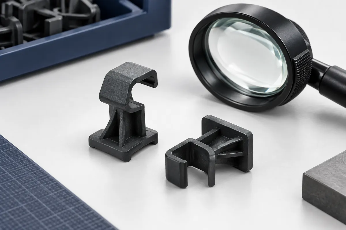
Then evaluate the clip's separate use requirements, such as repeated insertion and removal. An acceptable ejection check does not establish cycle life. Similarly, a service-cycle result does not retrospectively prove that an uncontrolled release method leaves every molded part undamaged.
Ask for a Route Decision with Visible Assumptions
A useful RFQ response shows the selected release concept, any required part changes, the trial checks and the unresolved risks. If neither route is satisfactory, reopening the geometry or parting strategy may be better than forcing a choice. The engineering owner should approve functional changes before tooling proceeds.
For custom molded clips and retainers, send the mating interface and permitted design changes with the CAD. Request a tooling review for your clip undercut. Use the illustrative releasable-clip study to organize the discussion without treating its sketches as a production-ready tool design.