
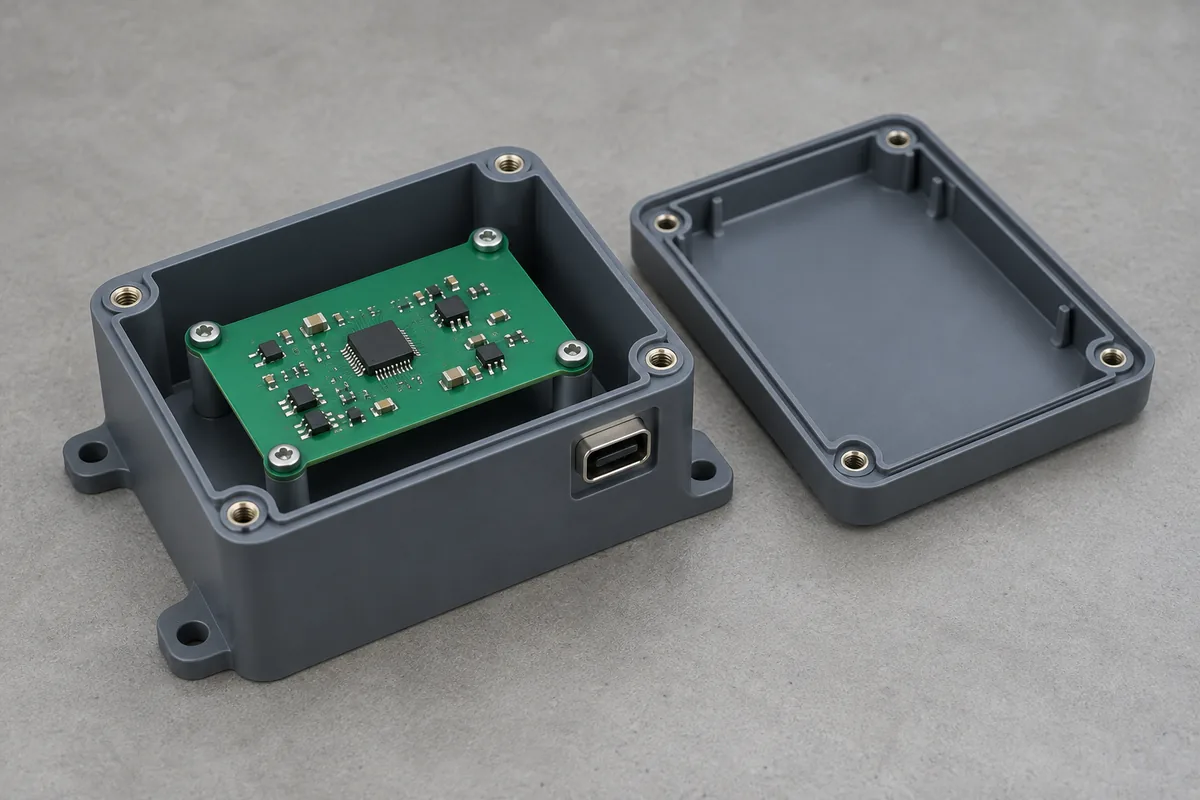
The PCB screws into the enclosure, yet a cable will not enter the connector cleanly. It is tempting to enlarge the opening immediately. Before changing the mold, check what positioned the board: its mounting holes, locating pins, support pads, or simply the order in which the screws were tightened.
PCB-to-enclosure fit is a chain of relationships, not a single opening dimension. The board must be supported, located and retained; the connector then needs an appropriate relationship to the housing wall and the mating cable. Treat these as separate functions before combining them in an assembly review.
Product design illustrations. Final geometry, materials and acceptance criteria are project-specific.
Support, location and retention are different jobs
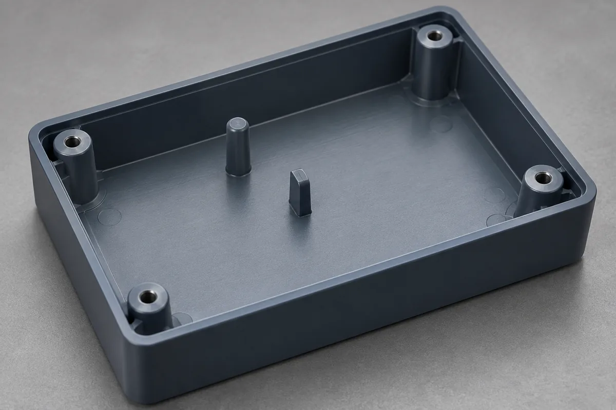
Support pads establish the board's seating plane. Locating features control the relevant sideways motion and rotation. Fasteners or clips retain the board against the intended supports. One feature can serve more than one job, but the drawing should make that intentional rather than leave it to assembly friction.
A clearance screw hole does not uniquely locate a board until something selects a position within the clearance. If two tight pins are intended to locate it, the separation of both pins and both board holes matters. Adding more close-fitting features can make an assembly harder to fit rather than better defined.
A round locator combined with a relieved secondary locator is one possible concept to review, not a universal prescription. The board drawing, moldability and required motion constraints decide whether it is appropriate. Protolabs' boss-design guidance describes bosses used for both fastening and locating; those functions still need their own controlled interfaces in an enclosure design.
Follow the connector back to a common reference
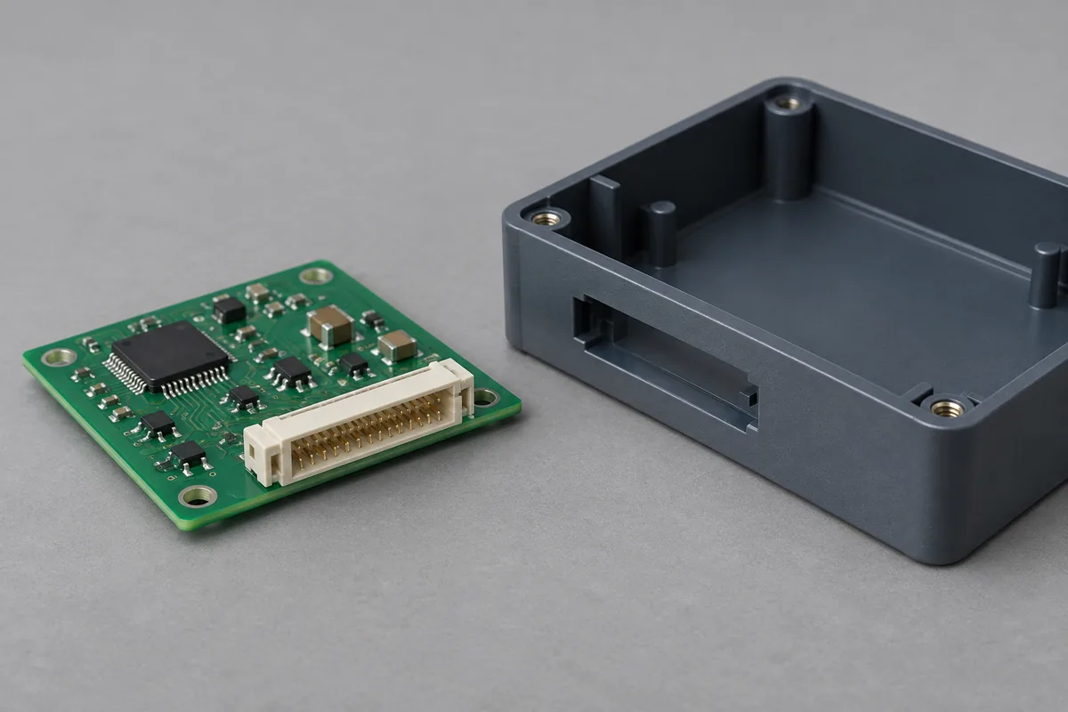
Begin at the housing datum or assembly reference. Follow the relationship to the board support and locator, then to the board mounting features, then to the connector's functional surface. Separately follow the housing reference to the opening. The difference between those paths is the alignment question.
Include the populated board, not just the bare-board outline. Component placement and the connector's own construction affect the interface. Obtain the controlled connector drawing and applicable placement requirements. A 3D envelope downloaded early in development may omit the details needed for an interference or cable-access check.
| Relationship | What to define | Common oversight |
|---|---|---|
| Support plane | Pad heights, board contact zones and permitted restraint. | Using a nearby rib as an unintended additional support. |
| In-plane location | Board features, locating features and their datum relationship. | Assuming loose mounting screws establish a repeatable position. |
| Connector alignment | Connector envelope and position relative to the board and opening. | Checking the board outline while ignoring component placement. |
| User access | Mating plug, insertion path and required access space. | Sizing the window for the receptacle but not the cable overmold. |
| Lid clearance | Component height, board seating and lid interior geometry. | Closing the lid by bending the board. |
Use a simple clearance calculation carefully
For an illustrative one-dimensional opening check, let the minimum window width be W, the maximum connector envelope be C, and the maximum center offset in the direction being checked be e. The smaller side clearance is (W − C) / 2 − |e|. This is a simplified geometry relationship, not a complete GD&T analysis or a recommended tolerance.
The formula explains why a generous-looking nominal opening can still interfere when the connector shifts toward one edge. It also shows why measuring only window width cannot establish alignment. Determine e from the actual drawing relationships and assembly freedom, rather than assigning a convenient number.
For the real assembly, consider rotation, corner radii, draft, connector protrusion and the mating plug's path. Choose worst-case or statistical methods according to the engineering requirements and available evidence. Do not claim a statistical yield from assumed distributions or a small handful of convenient samples.
Check the vertical stack separately
Board-support height, board thickness and the connector's mounting relationship determine its elevation. Inspect whether the board actually seats on every intended support before evaluating connector height. A trapped wire, excess screw engagement or an interference beneath the board can change the state being measured.
Then check the space above the assembly. A lid rib may contact a component before the perimeter seats. Tightening the cover to close the seam can conceal that contact while loading the board. For the closure side of the problem, see the lid-gap and warpage diagnostic guide.
Make the inspection reproduce the intended assembly
Measure the empty housing's relevant features, then evaluate an identified board and connector configuration. Preserve drawing revisions and sample identities. A fit check with a development PCB cannot automatically approve a later board with different mounting-hole or component-position requirements.
Document screw sequence and any specified tightening method when they influence the check. Record whether the board is free to float, lightly retained or fully fastened. If manual pressure is needed to align the connector, report it as an observation to investigate—not as a normal installation step unless the design expressly requires it.
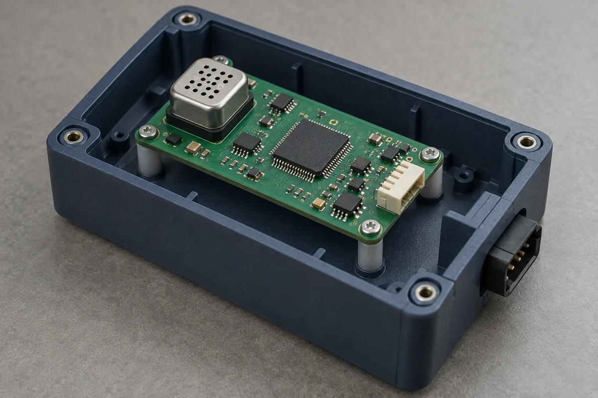
The resulting review should identify a specific change or evidence gap: a locating scheme, a support height, a connector definition or a window requirement. Our sensor enclosure design study follows this reasoning through a hypothetical assembly without inventing measured results. Send the housing, populated-board envelope and mating-plug information together when requesting a molding review.
Turn the review into a defined molding scope
Explore our custom injection-molded electronic enclosures and the related illustrative engineering study. Send the drawing revision, counterpart details, intended use and the decisions still open. Development samples and production approval should have separate, agreed deliverables.