
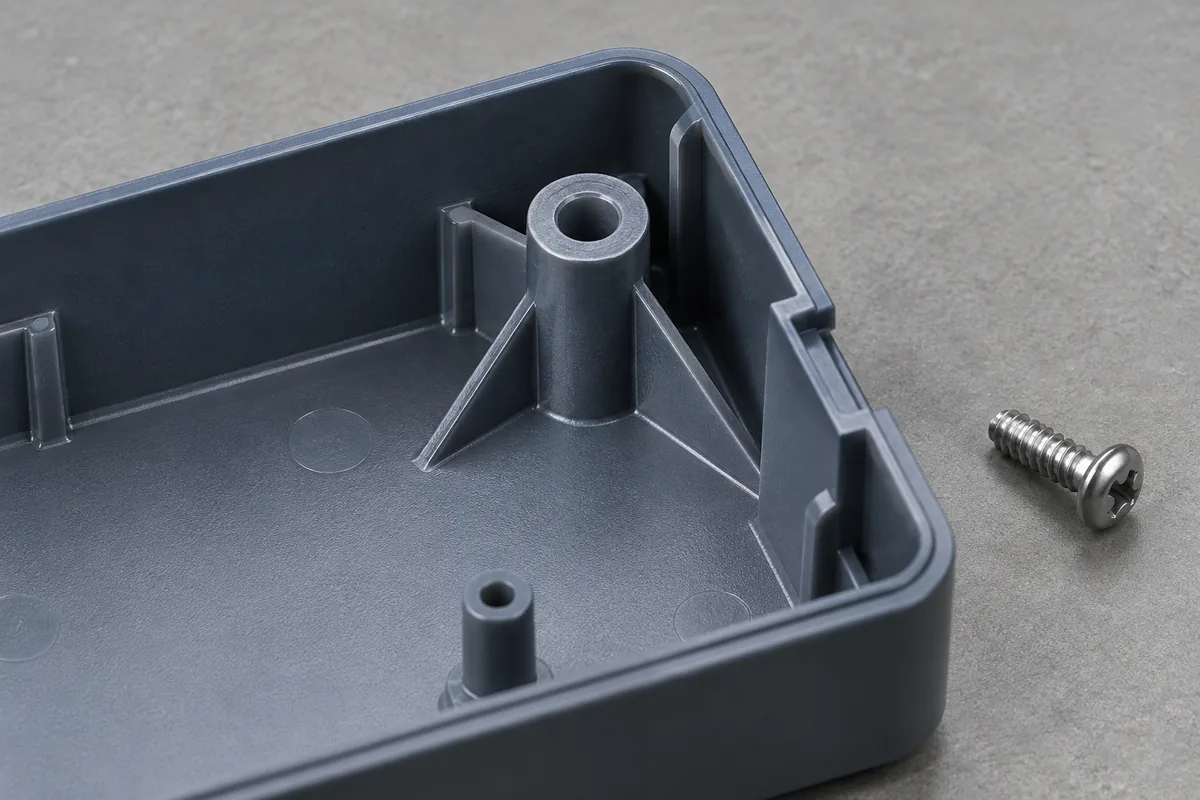
A cracked screw tower and a shallow depression on the outside of a housing may appear above the same feature, but they are not the same defect. Adding plastic to strengthen the tower can increase the local mass behind the visible surface. Making everything thinner to hide sink can leave the fastening function unresolved.
Investigate screw-boss cracking as a joint problem and sink as a local geometry-and-molding problem, then review their interaction. The useful change is the one that preserves the required joint while meeting the agreed appearance—not the one that improves one photograph.
Product design illustrations. Final geometry, materials and acceptance criteria are project-specific.
Find out when the crack first appears
Separate damage visible before assembly from damage created during screw installation, later tightening, service or chemical exposure. Preserve unassembled parts from the same identified group. A tower already damaged at ejection calls for a different investigation from a tower that splits only after a particular fastening operation.
Record the crack location and direction. Is it at the rim, root, a weld line, or an area affected by another feature? Keep photographs linked to the actual part and condition in a real investigation. The illustrations here show possible review locations; they are not evidence from a failed production batch.
Verify the screw and pilot hole as a matched system
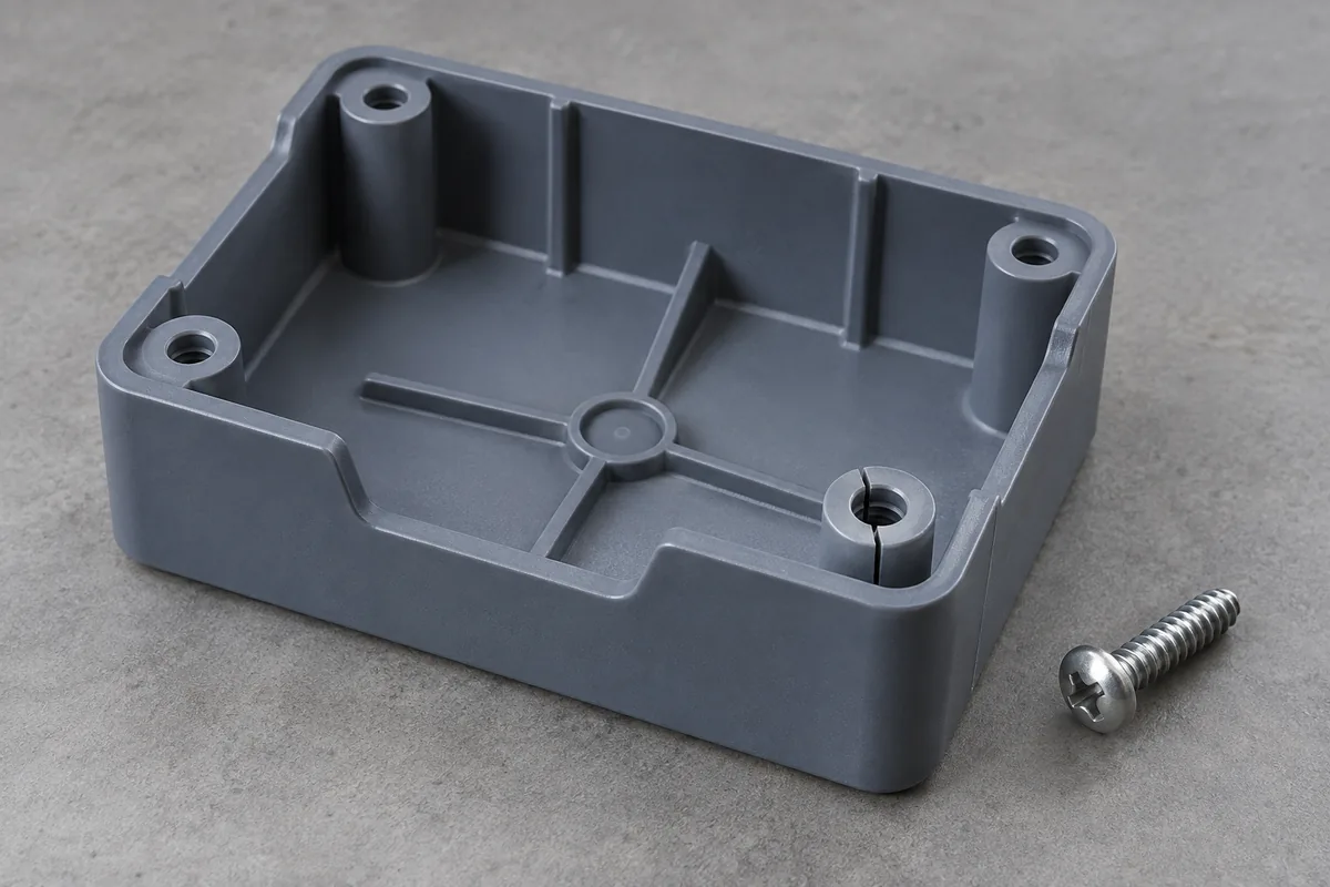
Identify the actual fastener: thread form, diameter, engagement length, head and supplier specification. Check whether the joint uses direct fastening into plastic or a threaded insert. A screw intended for a different material should not be accepted merely because it enters the hole.
Measure the relevant pilot-hole geometry in its specified state, including the effect of draft and the depth being evaluated. Confirm clearance at the bottom of a blind hole. A screw that bottoms before the intended joint closes can produce a misleading tightening response and an unintended load path.
EJOT's guidance on direct fastening in plastics treats the screw geometry and application engineering as part of a fastening system. Use the fastener supplier's recommendations for the selected plastic and joint, then validate the actual assembly. There is no universal installation torque that can be assigned from the enclosure's appearance.
Separate seating, thread formation and damage
Where direct fastening is used, the installation response includes more than the final tightening setting. Tool speed, alignment, engagement and the point at which the head seats can all be relevant. Ask what evidence is available from the actual assembly method before changing the nominal torque specification.
Define what the joint must retain and for how long. A lid opened repeatedly has a different brief from a permanently assembled housing. If service cycles are expected, include them in the evaluation. An insert may be worth reviewing, but it brings its own boss, installation and thermal considerations; it is not an automatic cure.
| Observation | First checks | Avoid this shortcut |
|---|---|---|
| Split during fastening | Correct screw, pilot hole, engagement, alignment and installation method. | Increasing the tower diameter before verifying the joint. |
| Damage before fastening | Molding, ejection, handling and local geometry; identified unassembled samples. | Blaming assembly torque for a pre-existing crack. |
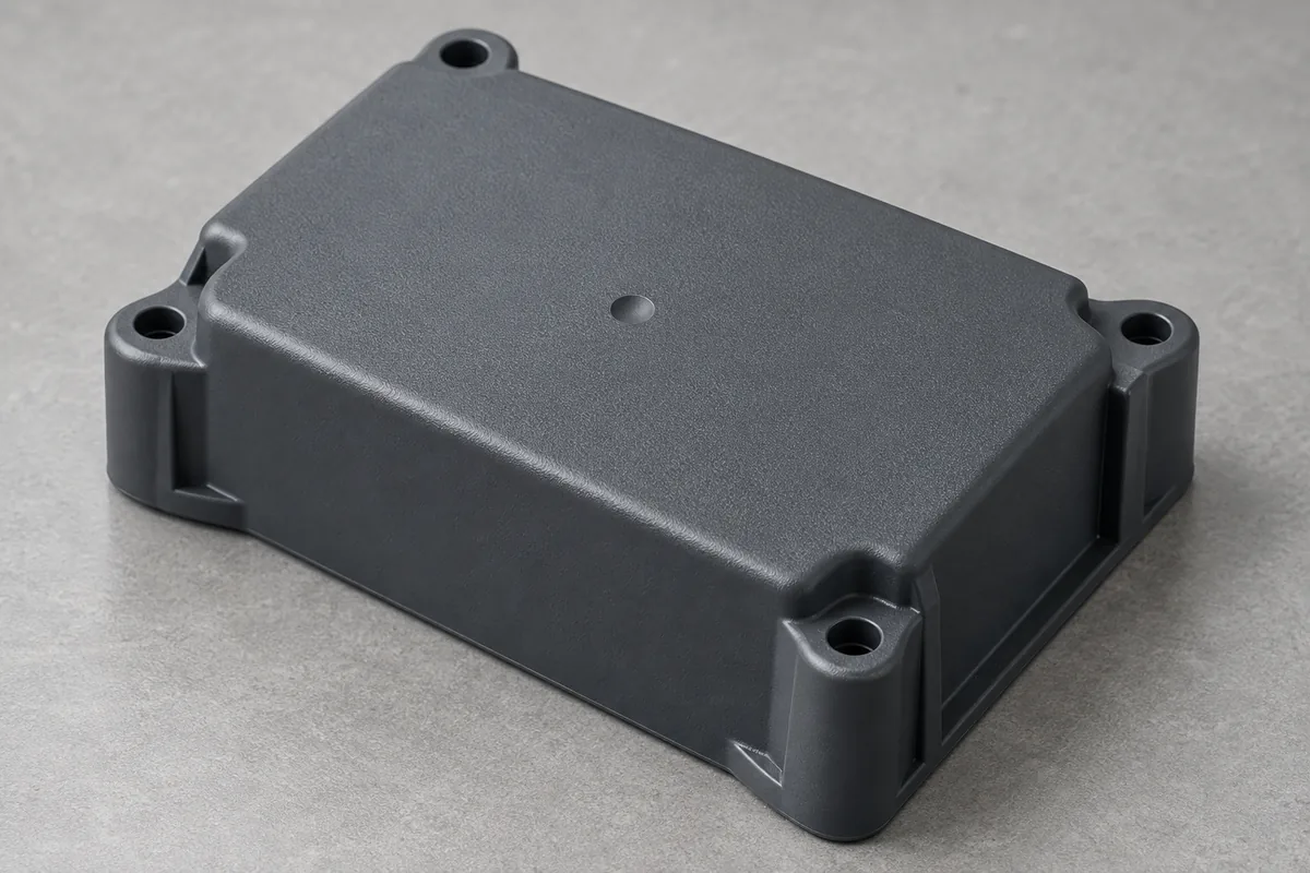
| Exterior sink above a boss | Local wall mass, feature transitions and the established molding condition. | Assuming texture will conceal every depression. |
| Delayed cracking | Assembly stress, temperature, chemical contact and material identity. | Changing resin without preserving the original exposure history. |
Look behind the cosmetic surface
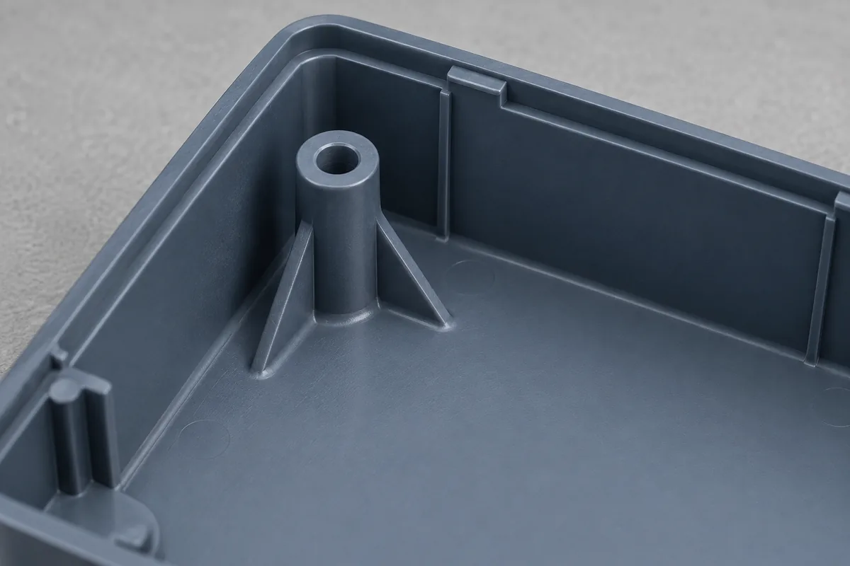
Examine how the boss joins the floor and nearby wall. A filled-in bridge can create a heavy local section even when the surrounding wall looks uniform. Review the cross-section, not only the outside diameter seen from above.
Protolabs discusses the tradeoff between boss support and sink risk, including the use of ribs rather than a large solid connection to an adjacent wall. Treat such guidance as a starting point for DFM. Required strength, resin, tooling access and the allowed cosmetic result still govern the actual design.
Do not prescribe a process adjustment from a photograph alone. The molding team needs the material, cavity, gate and process context to evaluate packing and cooling alongside the geometry. Preserve the initial sample condition so a later improvement can be attributed to the documented change rather than to several unrecorded adjustments.
Review a supported hollow boss instead of simply adding mass
A possible design direction is a hollow tower with deliberate support ribs, controlled transitions and separation from the outer wall where feasible. Check tool release, access to the hole and how the load enters the base. Supporting a tall tower changes more than its appearance.
Evaluate proposed geometry against both the fastening requirement and the visible-surface acceptance plan. A faint witness acceptable inside an industrial enclosure may be unacceptable on a handheld display surround. This boundary should be agreed before approving a revised tool feature.
Close the investigation with the right evidence
For cracking, retain the approved screw and installation specification, identified sample history and the agreed joint checks. For sink, retain the viewing conditions and representative appearance reference. If the resin or fastener changes, record a new configuration instead of treating it as the same trial.
The objective is a repeatable assembled housing with a defined appearance. A photograph showing no crack immediately after assembly is not a life result, and a smooth exterior is not a torque-capacity test. Keeping these decisions separate makes it easier to choose a change that genuinely addresses the enclosure's requirements.
Turn the review into a defined molding scope
Explore our custom injection-molded electronic enclosures and the related illustrative engineering study. Send the drawing revision, counterpart details, intended use and the decisions still open. Development samples and production approval should have separate, agreed deliverables.