
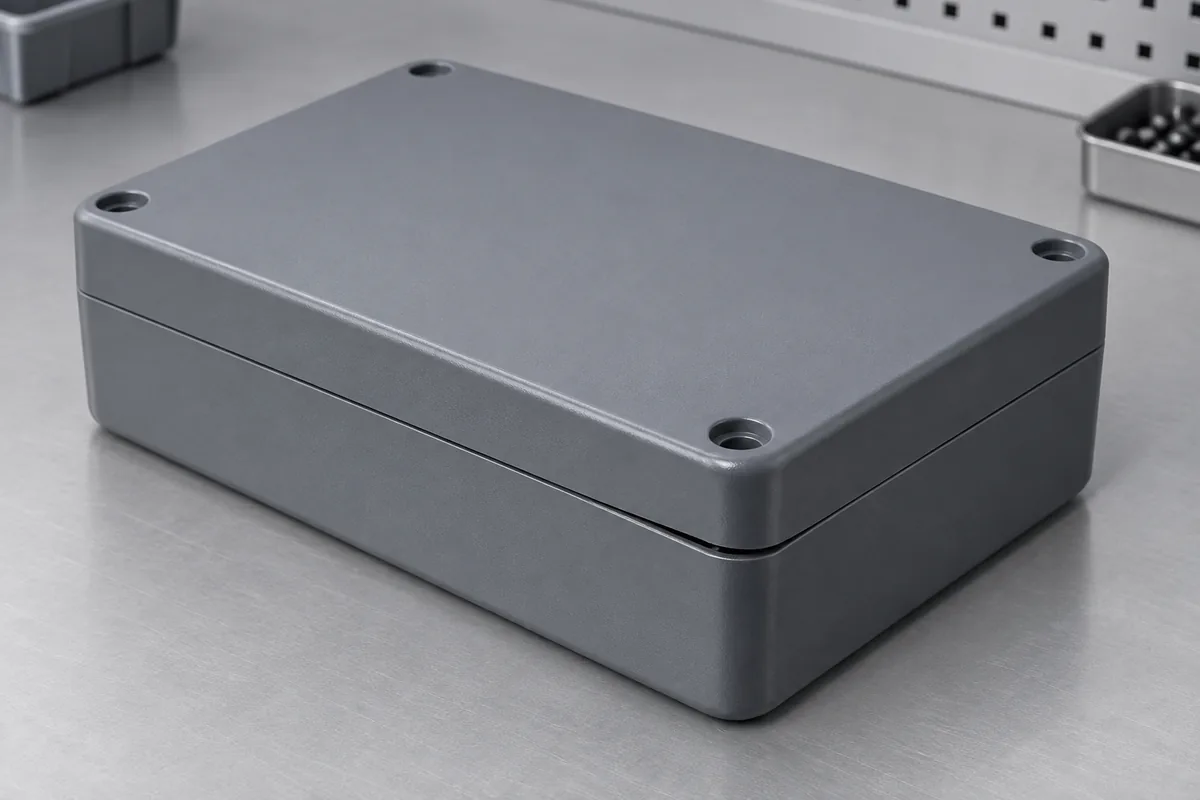
The lid sits high at one corner, so the first diagnosis is “warpage.” It may be correct. It may also be a locating lip that binds, a board that sits too high, a screw that bottoms, or a cable trapped across the joint. Tightening the cover until the gap disappears can hide the cause while creating a new load inside the product.
Check the empty, unrestrained components before the populated assembly, then add one defined constraint at a time. This separates component shape from interface interference and assembly effects. An uneven seam is an observation; it is not yet a root cause.
Product design illustrations. Final geometry, materials and acceptance criteria are project-specific.
Record the gap before changing the assembly
Identify the base and lid revisions, cavity IDs if available, material and sample history. Record where the gap is seen and in what state: freely placed, partially fastened or fully assembled. Use an agreed measurement method that does not force a flexible edge into a different shape.
Keep the original pairing identified while you investigate. Later, controlled cross-pairing can help determine whether an observation follows one lid, one base or a combination. Randomly swapping parts before recording the starting condition removes useful information.
Separate free-state shape from mating fit
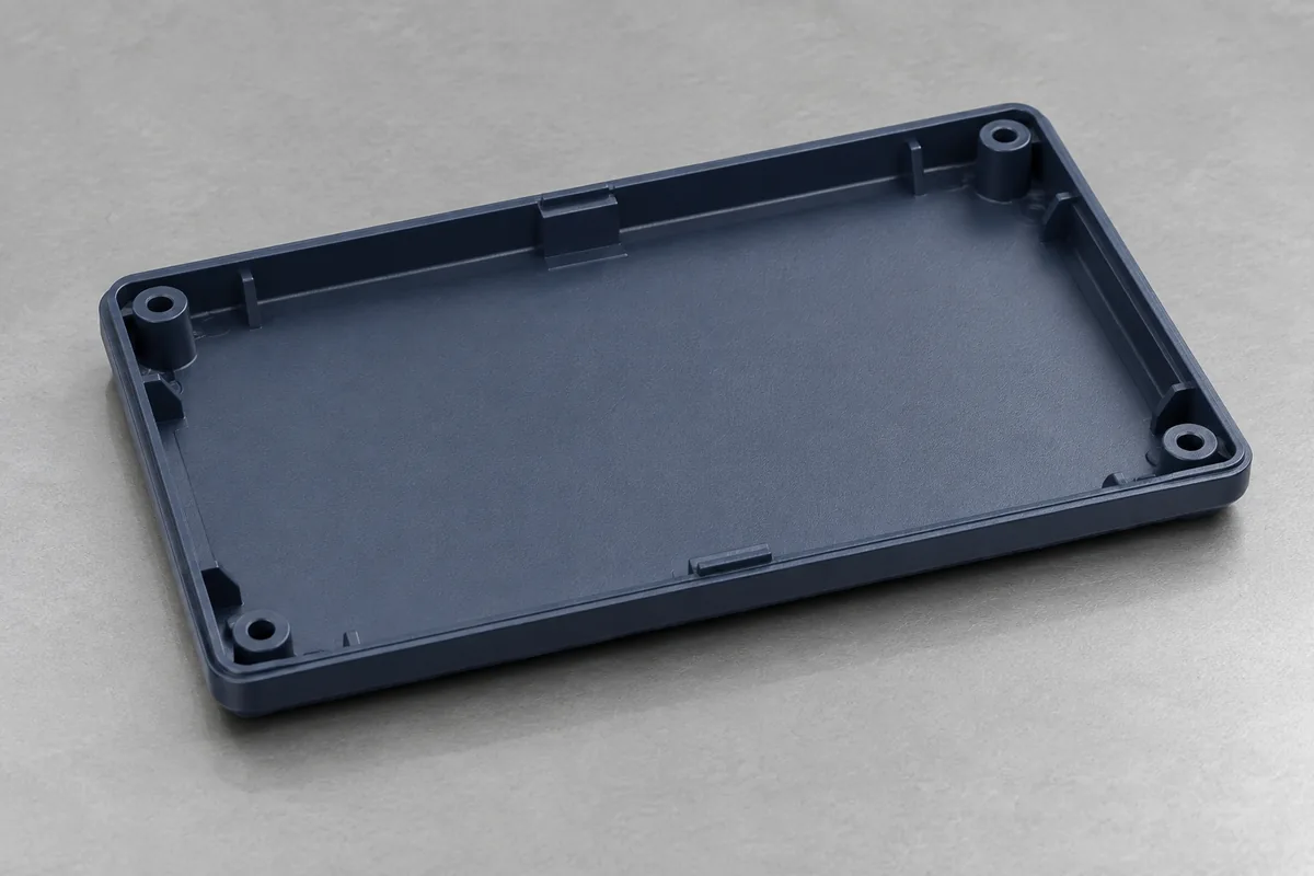
Evaluate the lid and base independently using support appropriate to the drawing and part geometry. A convenient flat bench does not automatically establish the specified datum condition. A thin cover can deflect under its own weight or light probe contact; document how the measurement is made.
Protolabs' molding design guidance explains why wall distribution and shrink-related effects can contribute to distortion. Those mechanisms are reasons to examine the molding and geometry, not proof that they caused a particular assembly gap.
If a component is outside its agreed free-state requirement, retain that result. If both components meet their individual requirements but do not mate, investigate the combined interface. Component conformance and assembly conformance answer different questions.
| Stage | What to observe | What it helps separate |
|---|---|---|
| Empty components | Base and lid shape under the defined support condition. | Free-state form from later assembly constraints. |
| Empty mating pair | Locating lip, rim contact and local interference without forcing. | Interface fit from PCB, cable or gasket effects. |
| Populated assembly | Board seating, component height, cable route and any seal. | Internal stack-up from empty-housing behavior. |
| Controlled fastening | Sequence, screw engagement, seating and specified tightening method. | Fastener effects from earlier contact conditions. |
Inspect the locating lip and rim
A perimeter lip can guide closure, but its clearance needs to accommodate the actual molded geometry and drawing requirements. Inspect corner radii, draft and local flash where engagement begins. A broad face may appear clear while one corner prevents the rest of the lid from seating.
Use the approved definitions of gap and flushness. Gap describes separation across the seam; flushness concerns the relative level of adjoining surfaces. A housing can have an even gap but an objectionable step, or a flush outer profile with local internal interference. Specify each relevant requirement instead of treating a photograph as both measurements.
Do not remove material from a sample and call the housing approved without recording the alteration. A marked relief can be a useful diagnostic experiment, but the modified sample now represents a different geometry. Keep the original result and the proposed drawing change separate.
Add the internal assembly deliberately
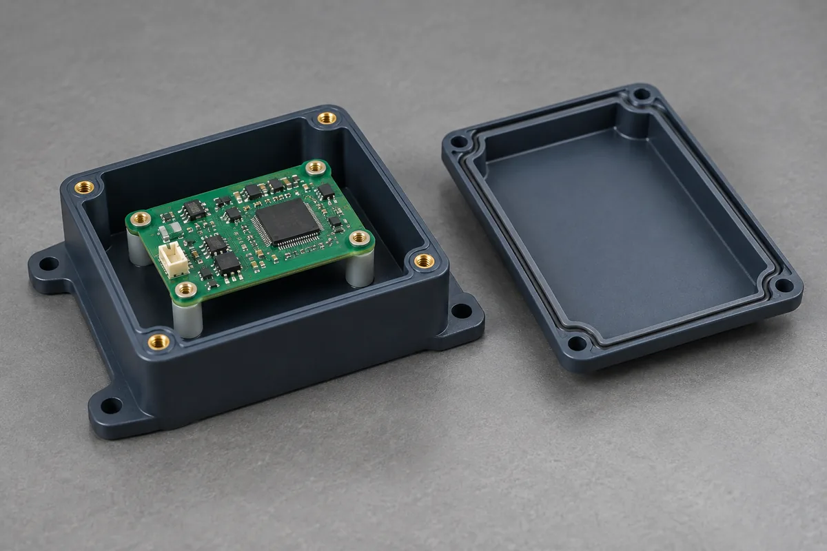
Check the board support plane and the height of components below the lid. Include connectors, buttons, cable bends and any gasket in the relevant stack. A compressed component can make the perimeter look acceptable while leaving stress elsewhere.
Document the insertion and closure sequence. If a wire must be moved aside for each assembly, that may be a routing question rather than an enclosure form problem. If the connector only aligns after the lid is tightened, revisit the PCB locating and connector-window relationship.
Use fastening as specified, not as a repair tool
Confirm that screw length and engagement allow the intended joint to close. Apply the approved sequence and tightening method, preserving observations before and after fastening. A screw that feels tight because it has bottomed does not demonstrate that the lid is clamped correctly.
Do not increase torque to compensate for an unexplained gap. This can load a screw boss, bow a board or change a seal condition. The screw-boss diagnostic guide covers joint-related checks that should accompany a fastening concern.
Choose the corrective action from the evidence
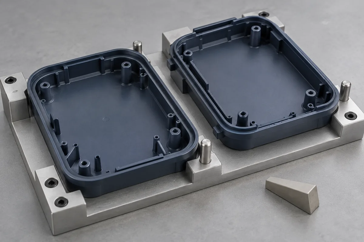
If the evidence points to molded form, review cavity, material, geometry and process history with the molding team. If it points to a lip, revise that interface deliberately. If it points to internal stack height or screw engagement, do not ask the toolmaker to compensate by distorting the enclosure geometry.
Recheck the changed configuration against the same acceptance method and preserve the part identities. For a sealed enclosure, dimensional closure is not an ingress-protection result; the complete assembly requires its own applicable evaluation. A good investigation ends with a defined cause and a verified change, not simply a seam that closes when enough force is applied.
Turn the review into a defined molding scope
Explore our custom injection-molded electronic enclosures and the related illustrative engineering study. Send the drawing revision, counterpart details, intended use and the decisions still open. Development samples and production approval should have separate, agreed deliverables.