
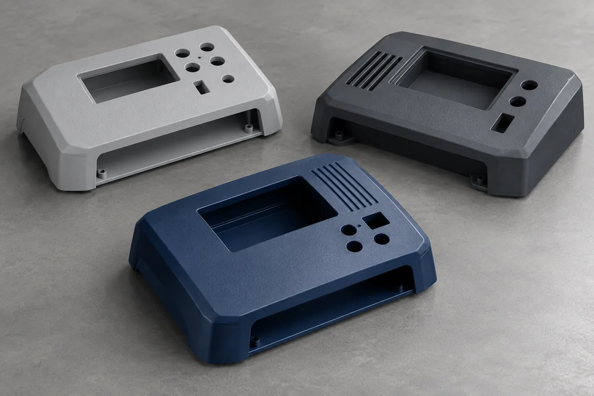
The sample is rejected for a mark the supplier considered normal. Both sides thought the drawing's “good cosmetic finish” note was clear. The problem is not necessarily that either side ignored quality; it may be that no one defined where, how and against what the appearance would be judged.
An enclosure cosmetic acceptance plan should connect surface zones, permitted manufacturing witnesses, viewing conditions and an approved reference. A texture code or color number alone cannot do all of that. Define the plan before tool finishing, while changes can still be discussed.
Product design illustrations. Final geometry, materials and acceptance criteria are project-specific.
Divide the enclosure by visibility and function
Mark the surfaces a user normally sees or touches, the sides visible only during installation, and internal surfaces hidden after assembly. Give these zones unambiguous identifiers on a drawing or marked model. A supplier should not have to infer the display face from a rendering that shows every surface equally well.
Keep cosmetic and functional limits separate. Flash on a hidden locating surface may disrupt assembly even though no customer sees it. A gate witness on an internal non-mating area may be visually unimportant but still need a height limit for clearance. Surface priority is not permission to ignore function.
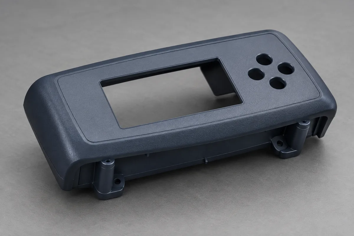
Specify a mold finish and approve the molded appearance
The tool surface influences the part, but it is not the finished plastic itself. Protolabs' cosmetic-design guidance notes that mold polish designations describe the tool surface and that resin choice affects the appearance reproduced on the part. This is why a finish callout should be paired with representative molded samples.
Name the texture system and exact designation when one is required. Identify where it stops, whether a smooth band surrounds an opening, and how transitions are treated. Ask about the draft and tool-release consequences before selecting a deep texture on a tall wall. Do not add texture late as a substitute for reviewing the underlying geometry.
A sample plaque can help choose a direction, but its wall, flow path and lighting differ from those of the actual enclosure. Approve the production-intent configuration for the relevant surfaces. The ABS versus PC/ABS guide explains why changing grade or color also needs an appearance review.
| Item | Define before sampling | Preserve at approval |
|---|---|---|
| Surface zones | Visible faces, touch surfaces, hidden areas and functional interfaces. | Marked drawing revision and zone-specific decisions. |
| Texture and gloss | Tool-finish designation, boundaries and required appearance. | Identified molded references and any instrument method. |
| Color | Target reference, exact grade/color and comparison conditions. | Approved sample identity and agreed variation criteria. |
| Manufacturing witnesses | Proposed gate, parting line and ejection locations. | Permitted condition or limits at each relevant location. |
| Viewing method | Lighting, distance, angle, inspection time and part state. | A reproducible procedure used by both parties. |
Agree how a mark will be viewed
Inspection under strong grazing light can reveal a surface variation that is not obvious in normal use. That does not mean one method is right for every product. Specify the intended method and use it consistently. If an additional diagnostic light is used to investigate a problem, identify it separately from the agreed acceptance view.
Set the part's condition as well: clean, assembled or unassembled, free of temporary protective film if appropriate, and at the agreed stage of handling. Dust, cleaning residue and packaging scuffs should not be confused with a molding feature. Record the observation without immediately assigning a cause.
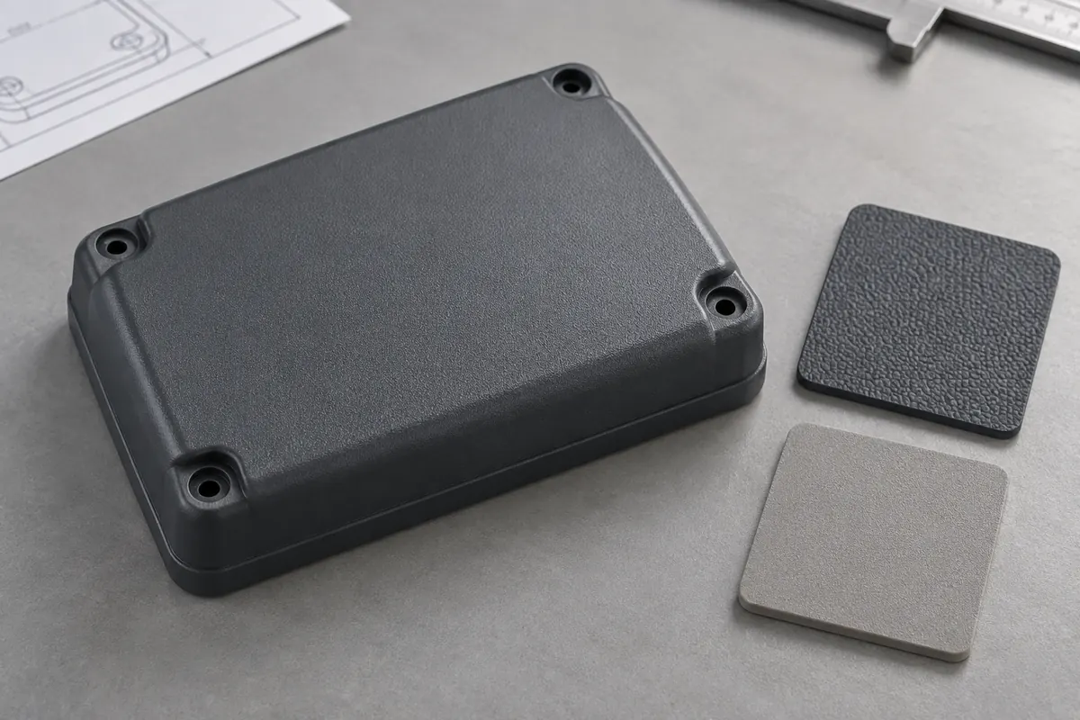
Treat color and gloss as related but distinct
Two enclosure halves may appear different because of shade, gloss, texture orientation or lighting. Start with a neutral comparison environment and the correct material and color records. A phone photograph, screen setting or browser rendering should not become the sole color-acceptance standard.
If instrumental color measurement is required, agree the instrument setup, reference, measurement locations and acceptance calculation. If visual comparison is required, define that method instead of inventing a numerical color limit after the samples arrive. Keep a method for resolving disagreements between a measured result and an appearance observation.
Use approved limits appropriate to the actual product. “No difference” is difficult to reproduce unless its meaning is defined. A matched enclosure set may require an assembly-level comparison even when each half is individually within its own agreed criteria.
Allow manufacturing features where they do least harm
Review proposed gate, parting-line and ejection locations with the molder. Mark no-go cosmetic zones and explain why they matter. An inaccessible hidden location may create tooling or filling difficulties, so a blanket demand for no witnesses anywhere is not a useful DFM instruction.
Discuss sink, weld lines and flow-related appearance in the context of geometry and material. A textured surface can still reveal underlying variation. Our boss and sink guide covers the common conflict between internal support features and the visible face behind them.
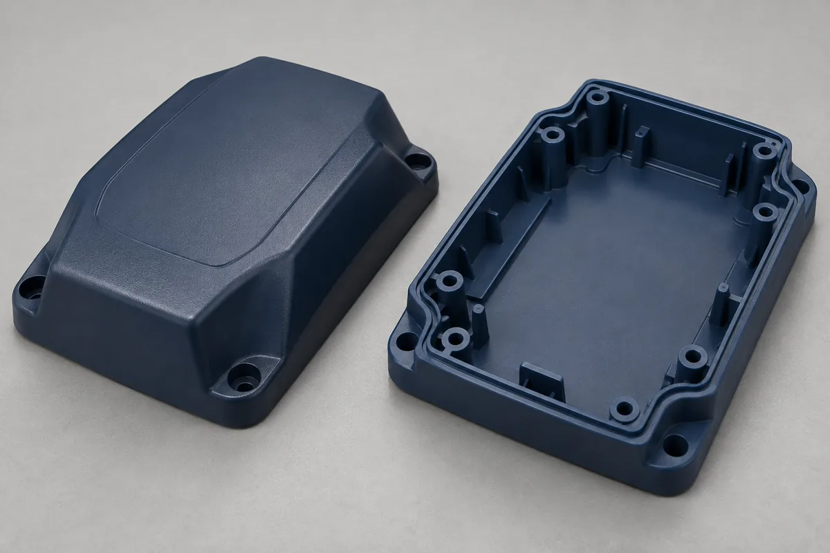
Keep the approved reference under control
Identify the approved samples by drawing revision, material/color and date, with the relevant cavity or run information. Preserve the limits and any accepted exceptions alongside the sample. A convenient part taken from a later shipment should not silently replace the original reference.
Define what triggers a review: resin substitution, color change, tool repair, texture refurbishment or a revised visible feature. Include handling and packing because a correctly molded surface can be damaged afterward. An effective cosmetic plan gives purchasing, molding and incoming inspection the same decision method, without pretending that appearance can be reduced to one vague adjective.
Turn the review into a defined molding scope
Explore our custom injection-molded electronic enclosures and the related illustrative engineering study. Send the drawing revision, counterpart details, intended use and the decisions still open. Development samples and production approval should have separate, agreed deliverables.