
Illustrative engineering study · September 24, 2026
Molded Spur-Gear Mesh: A Fit and Validation Design Study
A gear pair is an assembly relationship. Use a development fixture to understand the question, then evaluate the configuration that will actually be supplied.
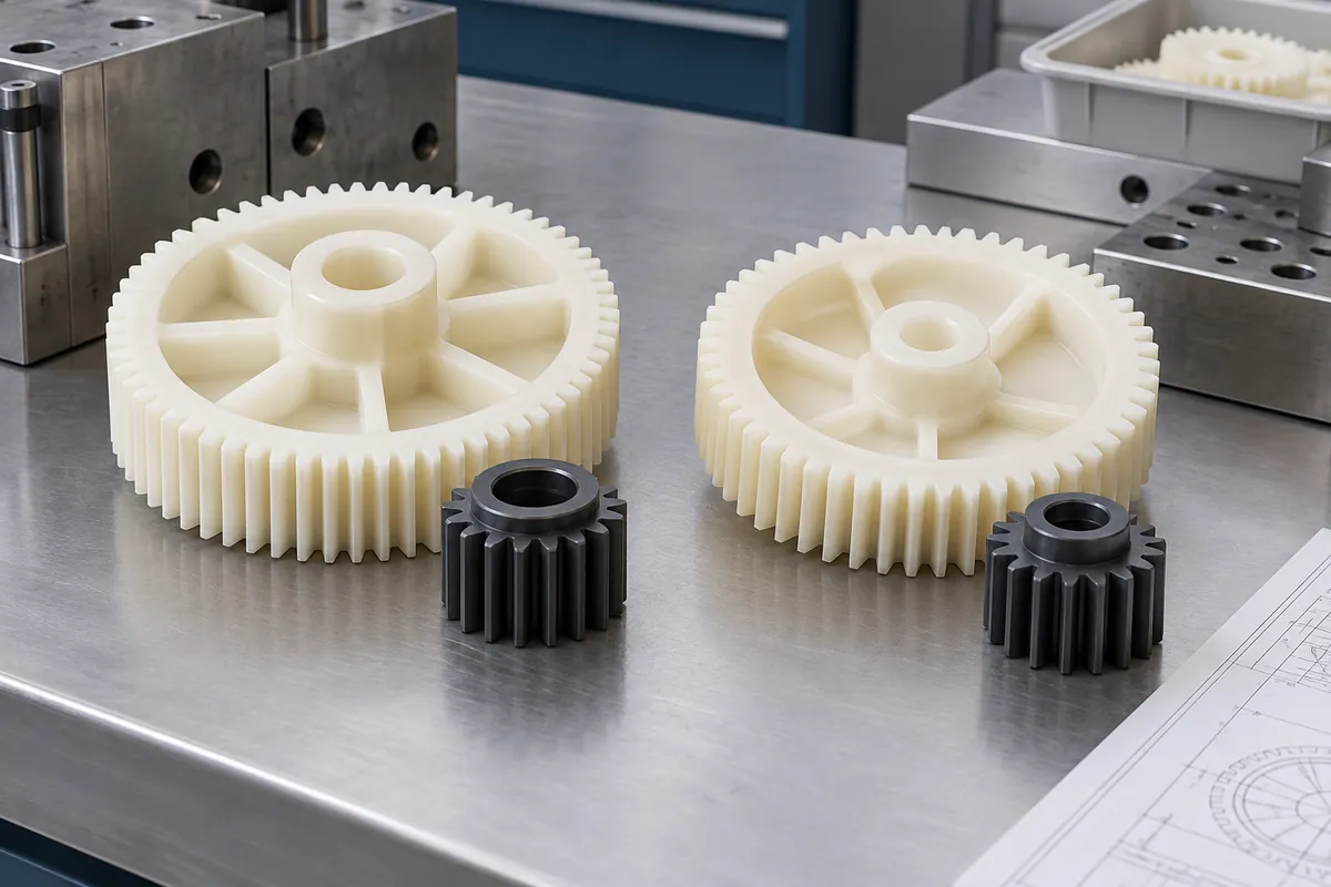
The design question
A free-running pair is not yet an approved mechanism.
Imagine a small equipment drive using a molded spur gear and a mating pinion. Tooth geometry and mounting interfaces are being reviewed before production tooling. The housing support, shaft fits and allowable center-distance variation are not yet approved. No resin grade, operating load or gear-accuracy class is assigned in this example.
A pair that turns freely in an open fixture can help expose an obvious fit problem. It cannot establish that the same pair will meet the required function inside its production housing. The fixture may have different alignment, stiffness, support and axial freedom. These differences belong in the record rather than being dismissed as laboratory details.
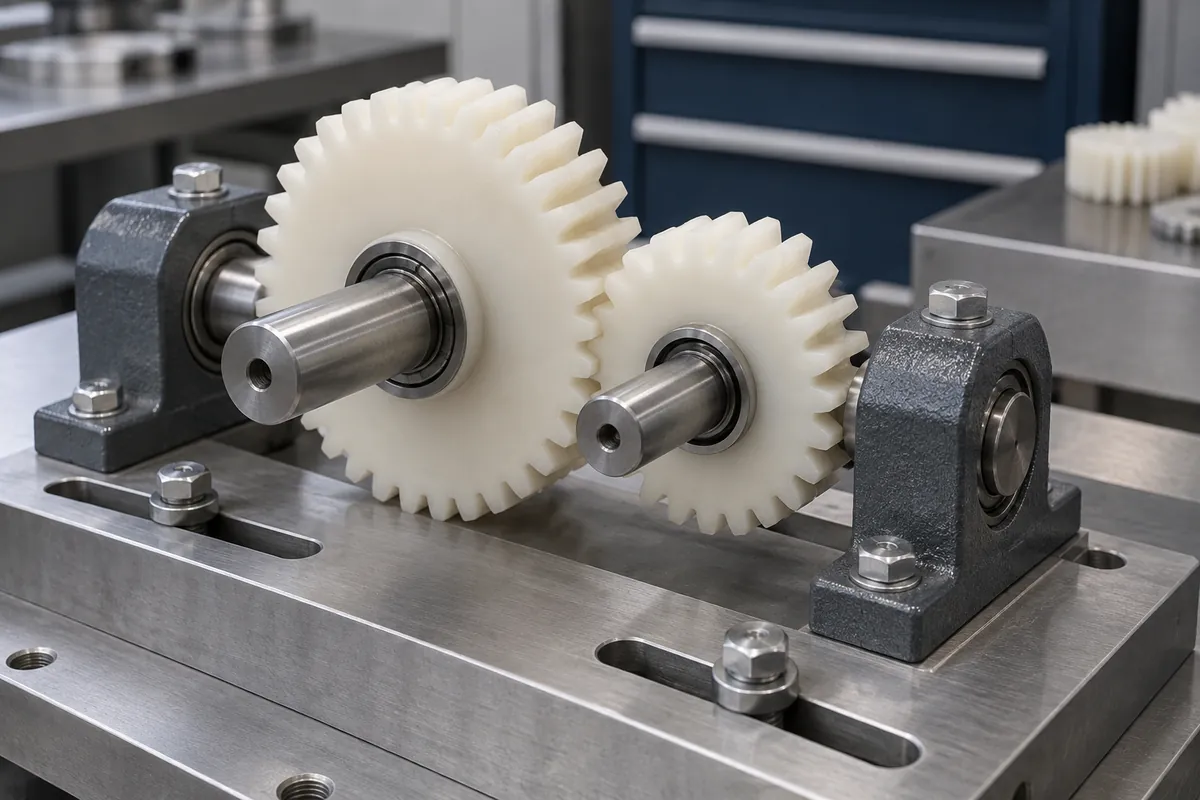
The study keeps the nominal tooth definition and intended duty common. It compares an adjustable development setup with a proposed fixed production-support arrangement. This is a comparison of what each setup can establish, not a claim that adjustment itself improves the gear.
The linked interfaces
Review teeth, mounting and supports together.
Provide the complete gear definition, counterpart revision, shaft interfaces and intended axial location. State the center-distance requirement and its permitted variation. The schematic uses circles as symbols, not manufactured involute tooth profiles or a verified mesh calculation.
In the adjustable setup, document each setting and the question it is intended to explore. A change in feel after moving the axes is an observation to investigate, not proof of an acceptable production limit. Do not transfer a fixture setting into a housing drawing without a design review.
In the fixed setup, inspect the actual support features and assembly state. If the gear bore, shaft or housing changes, identify a new configuration. The center-distance and backlash guide explains why a tooth-level requirement and an assembled clearance check must remain distinguishable.
Controlled comparison
Change one documented configuration at a time.
Start with identified parts and the same approved measurement condition. Record exact material, molding history, conditioning, counterpart and lubricant where applicable. A material change accompanied by a new gate, housing and shaft fit is a new configuration; it cannot isolate the effect of the resin alone.
Material screening should use exact-grade information and application requirements. Delrin's gear-material overview describes properties relevant to polymer gear applications, but it does not provide an application-specific rating for the hypothetical geometry shown here. A material brochure is not a completed drive calculation.
| Review area | Adjustable development setup | Production-representative setup |
|---|---|---|
| Purpose | Explore sensitivity and identify questions with documented settings. | Evaluate the actual approved mounting and assembly condition. |
| Part state | Identify each gear, counterpart, material and conditioning history. | Preserve the same traceability and identify production-relevant changes. |
| Mounting | Record axis position, alignment, restraint and fixture differences. | Confirm housing, bearing, shaft and axial-location requirements. |
| Decision | Screen concepts; report observations and unresolved questions. | Compare defined results with agreed acceptance criteria. |
Neither setup can answer every question. An accessible development fixture may support diagnosis that is difficult inside the housing. The housing can reveal constraints missing from that fixture. Use both only where each has a defined purpose, and avoid describing an exploratory observation as a qualification result.
Evidence plan
Inspect the part, then evaluate the operating system.
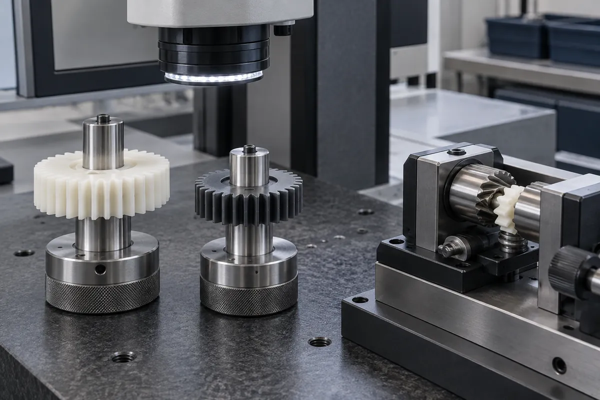
The inspection plan should distinguish tooth-related characteristics from bore, face and mounting features. Define the datum relationship, required report and method. If a gear standard or accuracy grade is required, identify its designation and edition and confirm how the agreed characteristics will be assessed.
Gleason's plastic-gear metrology overview lists several distinct measurement approaches, including analytical and composite checks. Their existence illustrates why the words “gear inspection” are not a complete acceptance specification. This reference is not a claim that FECISION owns or operates those systems.
The operating evaluation needs a separate protocol: load and speed history, direction changes, duty, environment, lubrication, measurement arrangement and stopping criteria. Noise measurements must define the surrounding assembly and background conditions. Wear observations need a specified location and method. Neither result can be supplied by a visual tooth check.
Decision boundary
The output is a testable configuration—not a rating.
Before a real release, the design owner must approve the gear definition, mating arrangement, material, inspection requirements and operating acceptance. Samples should remain linked to their configuration throughout evaluation. Any failure, interrupted run or out-of-limit observation needs its own disposition rather than removal from the comparison.
This study produces a review structure for a molded gear pair and its supports. It does not select a winning material, prescribe an allowable backlash or predict service life. A subsequent project can use the structure to decide which evidence is needed, which party supplies it and which changes trigger another review.
For purchasing, keep tooling, dimensional approval and operating validation as visible scope items. This lets quotations be compared at the same boundary and prevents an untested mechanism-level guarantee from being implied by the price of one molded component.
Apply the review to your part
Turn your drawing into a defined review.
Share the gear pair, mounting drawings and operating requirements. Identify what is already approved and what still needs engineering evaluation.
Explore our custom injection-molded plastic gears or the broader injection molding service.