
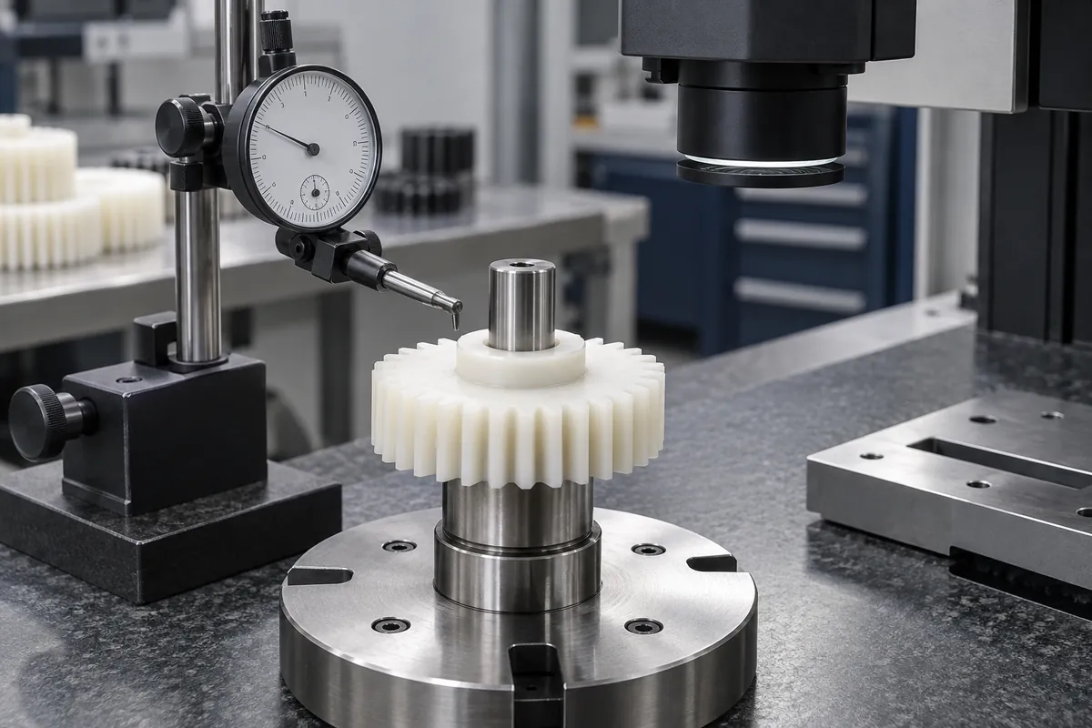
A gear inspection report can contain many dimensions and still leave the buyer unsure whether the teeth will work in the intended assembly. The opposite problem is a simple “rolls smoothly” statement that provides no traceable evidence about the bore, datum relationship or specified tooth characteristics.
Build the inspection plan from the drawing and the assembly function, then choose methods for each requirement. Component dimensions, tooth-system inspection and a mating check have related but different roles. This guide sets out the decisions to agree with the gear designer and inspection provider before trial samples are made.
Product design illustrations. Final geometry, materials and acceptance criteria are project-specific.
Identify the drawing's controlling references
Record the tooth definition, bore specification, side-face requirements and any stated accuracy standard. Include the applicable revision or edition rather than writing only “precision grade.” If the drawing omits a parameter needed for inspection, resolve it with the design owner instead of deriving an unapproved value from the model.
Define how the part will be supported and aligned. A gear intended to run on a bore may need a bore-related datum system, but the actual drawing governs. A convenient outside-diameter grip can introduce a different reference or distort the part. Document the mandrel or fixture and its contact with the specimen.
Separate mounting features from tooth features
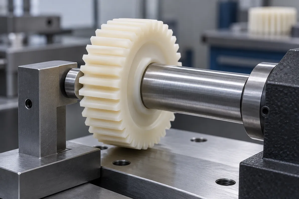
For the mounting interface, identify bore size and form, the locating face, hub features and any relationship to the tooth system required by the drawing. If there is an insert, include its location and relevant interface checks. A thread or bore gauge answers its own defined question; it does not establish every nearby feature.
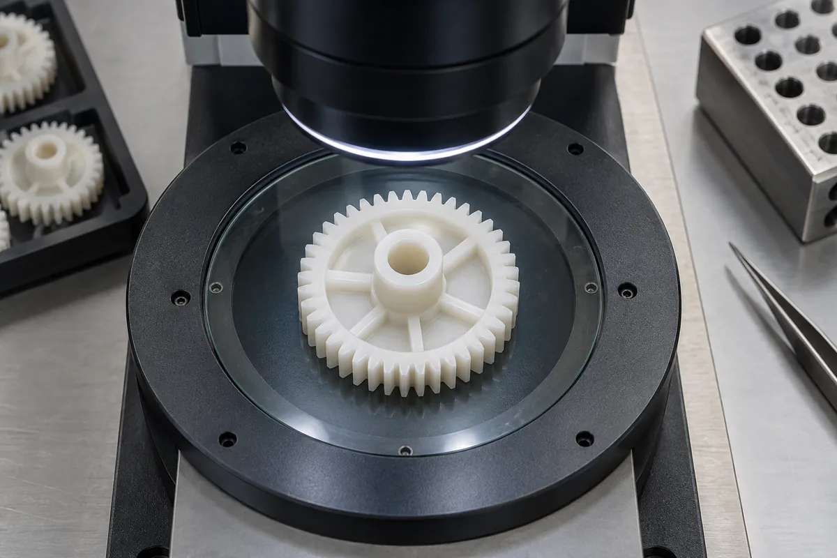
For the teeth, ask which individual characteristics are required and which equipment or method can evaluate them on the actual size and material. Do not assume that an optical outline comparison reports every tooth characteristic. Access, edge definition, draft and the selected measurement section should be understood.
The chosen method must preserve the definition of the characteristic. A report should identify the feature and result, not simply provide a collection of unlabeled coordinates. If software fits a geometric element or uses a particular alignment, retain that method with the inspection program revision.
Understand what a combined rolling check adds
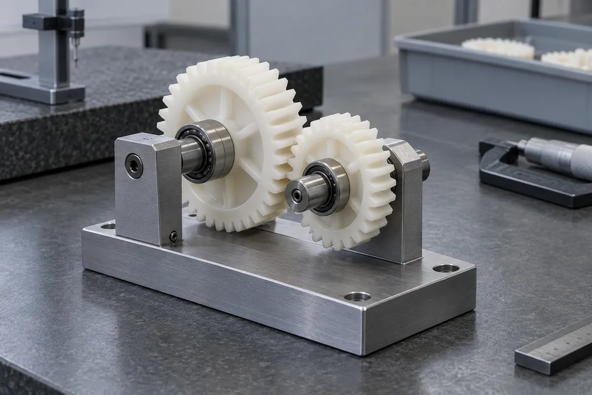
A controlled rolling or mating check can evaluate a combined behavior of the gear pair. Its meaning depends on the test type, the master or counterpart, mounting and load. It should be specified by a qualified gear-inspection provider rather than treated as an informal hand-spin test.
Keep the check's result separate from individual feature results. A combined response may reveal a problem without uniquely identifying its cause. Conversely, a selected set of individual dimensions may not reproduce the assembled condition. The backlash review provides the mounting context needed to interpret a mating observation.
| Group | Agree before inspection | Keep with the result |
|---|---|---|
| Mounting geometry | Bore, hub, side-face and datum requirements. | Fixture, alignment and feature IDs. |
| Tooth characteristics | Drawing-defined characteristics and applicable standard. | Method, program revision and individual results. |
| Combined check | Test type, master or counterpart and support condition. | Counterpart ID, setup and defined result. |
| Sample history | Cavity, resin, conditioning and collection interval. | Sample IDs linking all reports. |
Control the specimen condition
State the interval and environment for measurement after molding and any conditioning required by the application. Identify the resin grade and sample history. For a material comparison, do not mix reports from different states without labeling the difference. Otherwise, a change in condition can look like a change in manufacturing accuracy.
For multi-cavity output, preserve cavity-level results before pooling them. Decide the sampling plan based on the required confidence and production arrangement with the quality owner; this guide does not invent a universal sample count. Mark which specimens were used for destructive or endurance tests so that the record remains coherent.
Verify the method, not only the instrument
Gleason's plastic-gear metrology overview distinguishes analytical, optical and composite approaches. Select the method for the characteristic being accepted; one type of check does not automatically replace the others. This is a reference to available methods, not a claim that FECISION operates those systems. Also address equipment verification, repeatability, handling and fixture suitability. An instrument's specification does not remove uncertainty caused by an unstable setup or ambiguous feature definition.
Resolve discrepancies with the original records intact. If a measurement is repeated after a method correction, retain the reason and identify the replacement result. Do not remove an inconvenient specimen from the sample group without a documented disposition.
Keep inspection separate from operating qualification
A drawing-compliant sample may still require wear, noise or endurance evaluation in the real drive. Conversely, a short successful run does not waive drawing requirements. Specify the relationship between component approval and system qualification in the gear RFQ.
The release package should make the conclusion narrow and clear: which parts, which revision, which condition and which requirements were assessed. No load rating, lifetime or acoustic guarantee should be inferred from a dimensional report that did not evaluate those outcomes.
Turn the review into a defined molding scope
Explore our custom injection-molded plastic gears and the related illustrative engineering study. Send the drawing revision, counterpart details, intended use and the decisions still open. Development samples and production approval should have separate, agreed deliverables.