
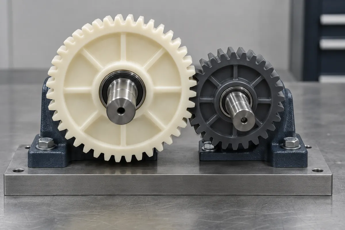
A molded gear pair turns freely on a bench fixture but binds when installed in its housing. Another pair runs smoothly in one direction yet produces unwanted movement when the drive reverses. In both situations, measuring the outside diameter of one gear is unlikely to explain the whole problem.
Backlash belongs to the assembled gear relationship. It depends on the defined tooth geometry, the mating pair and their actual mounting arrangement. For a polymer system, the relevant operating and conditioning states also belong in the review. There is no universal backlash value that can be copied safely into every molded-gear drawing.
Product design illustrations. Final geometry, materials and acceptance criteria are project-specific.
Define what you mean by backlash
State the quantity being measured, the location where it is expressed and the method used to hold or load the mating member. A small rotation at one shaft and a linear clearance at a tooth flank are not interchangeable numbers without the appropriate geometric relationship. Avoid comparing unlabeled readings from different setups.
Keep backlash distinct from tooth-tip clearance, shaft bearing play and axial movement. A measurement at the output can include several sources of lost motion. If the requirement concerns the complete mechanism, measure that system-level quantity, but do not automatically assign all of it to the molded teeth.
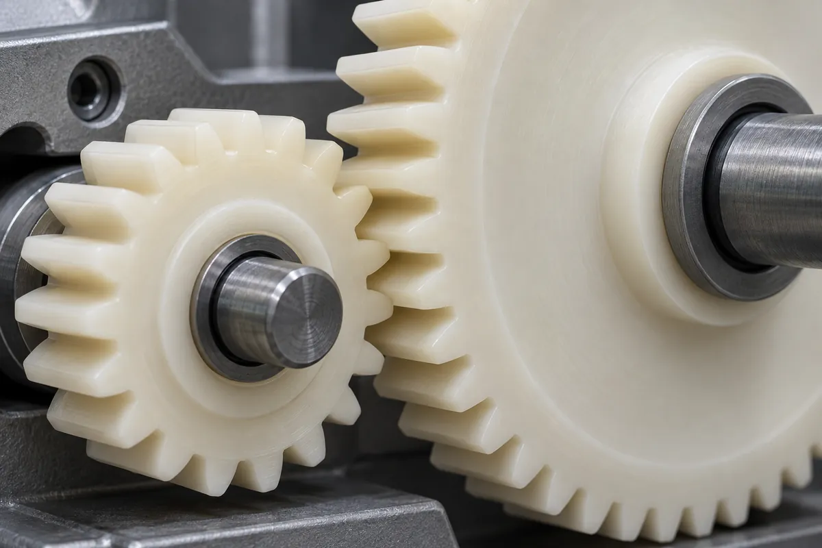
Bring the housing into the tolerance review
List the features that locate each shaft: housing bores, bearings, pins, mounting faces and any adjustable supports. Their combined variation influences the operating center distance and alignment. The nominal CAD arrangement is only one configuration within that assembly relationship.
For a preliminary design discussion, distinguish the nominal arrangement from the combinations that bring the gears closer together or farther apart. Have the gear designer evaluate the actual tooth system at the relevant limits. A generic arithmetic stack is not a substitute for a gear calculation, especially where profile modifications or nonstandard geometry are involved.
Also check how the housing is fastened during measurement. An open, loosely supported housing may not reproduce the installed state. Record covers, screws and supports that affect location; otherwise, a bench result and an assembled-product result can describe different systems without anyone realizing it.
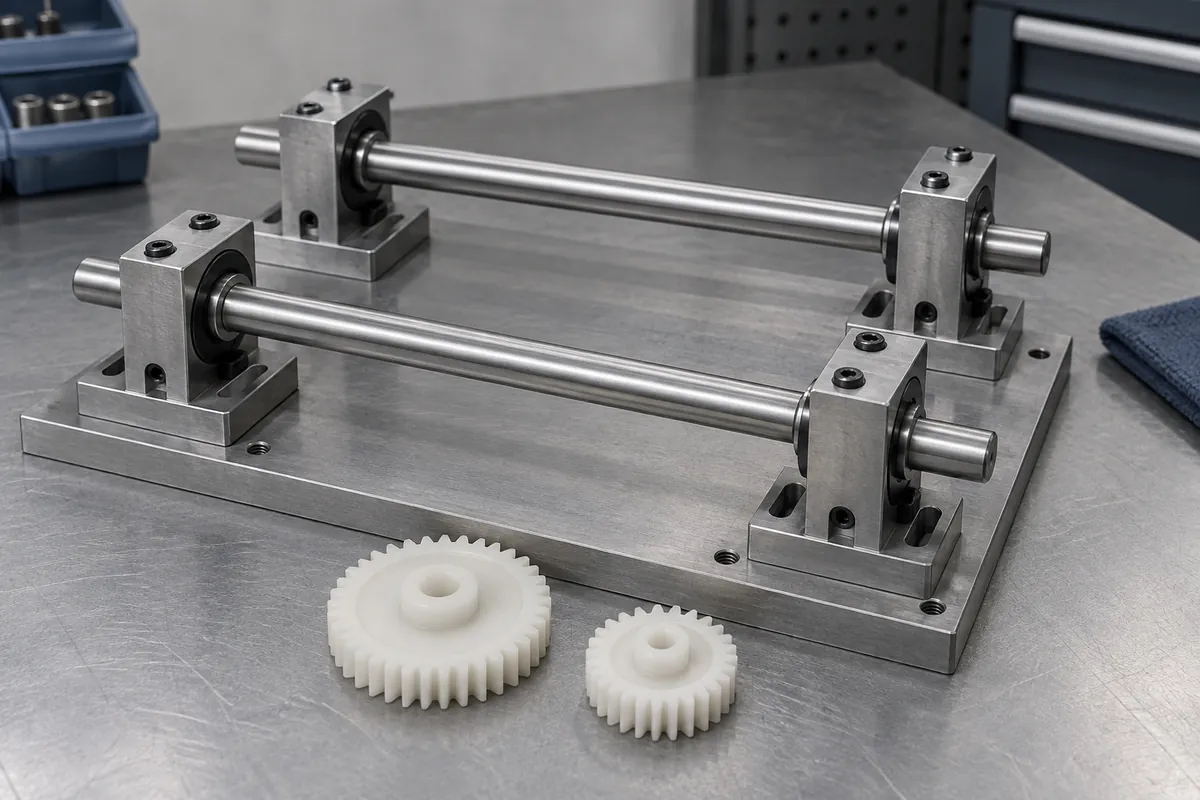
Include the material condition and temperature
Polymer dimensions and response should be evaluated in the intended environment. KHK's plastic-gear technical guidance warns of temperature and humidity effects for its plastic miter gears. That supports asking the environmental question; it does not provide a ready-made clearance for a different custom spur-gear design.
For a nylon candidate, distinguish dry and conditioned states; for any candidate, consult exact-grade data. Include the housing and shaft materials rather than considering only one polymer wheel. The relevant question is how the complete geometry changes in the specified condition, not whether the resin is generally marketed as stable.
| Area | What to identify | Why it matters |
|---|---|---|
| Gear pair | Both revisions, tooth definitions and material grades. | The acceptance concerns a pair, not an isolated wheel. |
| Mounting | Shaft supports, center distance, axial location and housing state. | A different support setup changes the relationship being measured. |
| Condition | Temperature, conditioning and lubrication state. | Keep comparisons tied to known application conditions. |
| Method | Held member, measurement location, loading and instrument. | Different measurement definitions can produce incomparable numbers. |
Investigate tight spots around a full revolution
Do not check only the angular position that feels best. Where the inspection method calls for a rotational assessment, preserve the relationship between angular position and observations. A repeating tight region can prompt investigation of runout, bore location, tooth variation or support alignment; it does not prove one cause by itself.
Keep the original gear pair together during the investigation. Swapping several gears and shafts at once may make the symptom disappear without revealing why. Introduce controlled changes, record what changed and retain the earlier configuration long enough to compare evidence.
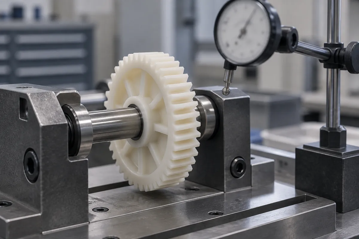
Put acceptance on the drawing or inspection plan
The design owner should specify the requirement, applicable condition and method. If an early development trial uses an exploratory range, label it as such. Do not turn the range that happened to work in a short trial into a universal production tolerance without the necessary review.
Separate incoming component inspection from the assembled drive check. The molded-gear inspection guide covers component evidence, while the wear and noise validation guide addresses operating behavior. The related design study shows how a controlled center-distance review can organize the questions before any measured outcome exists.
Turn the review into a defined molding scope
Explore our custom injection-molded plastic gears and the related illustrative engineering study. Send the drawing revision, counterpart details, intended use and the decisions still open. Development samples and production approval should have separate, agreed deliverables.