
Silicone Bellows: Stroke and Pilot Review
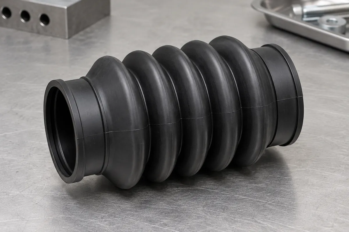
A silicone protective boot was developed for a moving mechanism with defined end attachments. The review focused on fold-root geometry, collar features and the difference between reaching the required positions and completing an endurance qualification.
The project record describes a 500-piece pilot. Dimensional and movement observations are reported below, while the cycle program remains open and is not promoted as a completed life rating.
4 cavities
LSR molding tool
40–120 mm
Recorded installed length range
500 pieces
Pilot batch
Project background
Component, scope and current phase
| Application | Protective boot for an equipment mechanism; customer machine details withheld |
|---|---|
| Material | WACKER ELASTOSIL LR 3003/50, black formulation; nominal 50 Shore A |
| Nominal geometry | 20 mm inside diameter, 26 mm outside diameter and 80 mm free length |
| Motion definition | 40 mm compressed installed length and 120 mm extended installed length |
| Manufacturing | Four-cavity LSR molding |
| Current phase | Pilot; customer endurance validation ongoing |
Engineering challenge
What the development work needed to resolve
The development record focused on cracking near fold roots and the end-interface condition. These areas connect the constrained collars to the moving wall, so the profile and attachment needed review together.
Free length, compressed length and extended length were recorded separately. This prevents the 40 mm and 120 mm figures from being misrepresented as independent one-direction stroke ratings or as evidence of qualified combined motion.
Manufacturing review
Changes and the verification approach
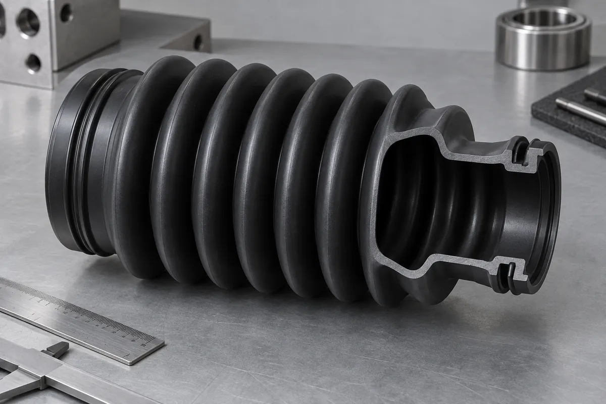
The recorded changes included a fold-root radius increase from 0.5 to 1.0 mm, revised end sealing features and a nominal hardness change from 40 to 50 Shore A. The case does not claim that a harder compound automatically provides a particular fatigue improvement.
Pilot inspection checked dimensions and hardness, followed by a limited movement evaluation using the intended length positions. The ability to reach those positions was kept separate from repeated-cycle acceptance.
The source summary uses inconsistent motion terminology for the continuing fatigue fixture. Its cycle count is therefore not published as an axial, bending or combined-motion qualification. The current public conclusion is limited to the clearly described checks and the open endurance status.
T0 · June 10
100 pieces
T1 · July 5
300 pieces
Pilot · September 1
500 pieces
Recorded observations
Results with their sample and test boundaries
Each result below applies to the stated specimens and configuration. Development, pilot and production checks are not combined into a single pass rate.
These are owner-supplied project summaries, not independently certified test reports.
| Check | Samples and conditions | Recorded observation | Interpretation boundary |
|---|---|---|---|
| Free-state dimensions | September 5 pilot sample; 20 specimens | Inside diameter 19.9–20.1 mm; free length 79–81 mm | Sampled dimensional record |
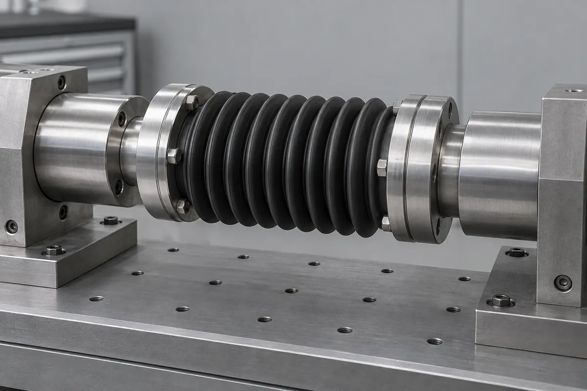
| Movement check | September 8; 10 specimens | Reached 40 mm compressed and 120 mm extended positions; recovery without visible cracking reported | Limited movement observation, not a fatigue-life result |
| Hardness | 20 sampled specimens | 48–52 Shore A | Project measurement summary |
| Endurance status | Customer cycle program in progress | Qualification remains open | No completed one-million-cycle or combined-motion claim |
Release status
What is established and what remains open
As of October 3, customer endurance validation remained ongoing. The publication does not assign a completed cycle life, oil-resistance rating or ingress-protection classification.
Final approval needs the actual motion mode, attachments, venting and environment to remain tied to the test record. A manual stroke check is not a substitute for that program.
Published anonymously with the project owner's permission. Original test reports and project photographs were not supplied for this publication review. Images are product design illustrations; no customer or supplier identity is displayed.
Related guides
Plan the next component review
- Silicone Bellows Design: Convolutions and Usable StrokeSpecify silicone bellows free, compressed and extended lengths separately. Review convolution clearance, end attachments and actual motion before assigning usable stroke.
- Silicone vs TPE Bellows: Motion, Exposure and Process ChoiceCompare silicone and TPE bellows using exact compounds, operating exposure, motion, end retention and manufacturing route. Avoid choosing by softness alone.
- Bellows Attachment: Clamps, Flanges and Molded Sealing LipsDesign bellows clamps, flanges and sealing lips around retention, compression, installation and motion. Distinguish a protective cover from a validated sealed assembly.
- Vented vs Sealed Bellows: Managing Trapped AirReview vented and sealed bellows through changing volume, trapped air, contamination paths and actuator load. Define the protected boundary before adding a vent.
- Molding Silicone Bellows: Undercuts and DemoldingReview silicone bellows undercuts, parting lines, release strain and tooling choices. Flexible material does not make every convoluted shape easy to demold.
- Bellows Fatigue Tests: Axial Motion Is Not Lateral MotionSeparate axial, lateral, bending and combined bellows fatigue tests. Report actual motion, fixtures, cycle count and interim observations without inventing service life.
Review your component and its mating assembly
Send the drawings, operating conditions, quantities and acceptance methods to define tooling, molding and inspection.