
Overmolded Grip Edge Retention: Two Concepts to Validate
A return lip or a through-feature anchor? Compare the design questions before asking a supplier to quote a soft-touch grip.
Evidence scope: Illustrative study, not a completed customer project.
Review scope and assumptions
The geometry and validation plan are conceptual, not a completed customer project. No delivered quantity, selected material grade, measured result or production outcome is claimed. Diagrams are not to manufacturing scale.
Process
Overmolding
Material
Substrate and soft overmold grades to confirm
Application
Overmolded Grip
The decision to investigate
How should the grip stay attached at its edge?
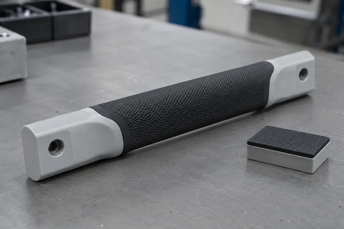
Assume a rigid plastic handle with a softer injection-molded grip. Its exposed edge may be caught during handling or wiping. The buyer wants to compare two retention concepts without deciding in advance which one will perform better. The handle is not assigned a safety-critical, medical or food-contact use in this illustration.
Custom overmolding can combine a compatible material interface with mechanical retention features. Protolabs describes wraparound geometry and holes as different ways to mechanically retain an overmold, and discusses protecting edges where peeling may begin. These general principles inform the alternatives below; they do not validate either proposed grip. Source: Protolabs overmolding design guide.
Does the intended material pair adhere under the agreed process and exposure? Does the complete geometry retain the grip under the intended loading? An anchor can still hold a grip after local interface separation, so one full-part pull result cannot answer both questions.
Two conceptual sections, not tooling drawings
The sketches isolate a single feature for discussion. They omit gates, vents, radii, draft, tolerances and tooling motions. The actual part needs a complete three-dimensional DFM review before either concept is considered manufacturable.
- Rigid substrate
- Soft overmold
Return lip around an edge
Question to resolve: Can the return be formed and released without damaging the grip or interfering with the assembly?
Through-feature anchor
Question to resolve: Can the anchor fill, release and be inspected while preserving the substrate and assembly requirements?
Original schematic illustrations. Not to manufacturing scale; no approved dimensions, selected resin grades or demonstrated performance.
Compare the questions that change the tooling quotation
These are review prompts, not a scorecard declaring a winner. Avient's overmolding guidance treats mechanical interlocks, shutoff design, tooling and processing as related design topics. The following matrix applies that review structure to these hypothetical shapes. Source: Avient overmolding guide.
| Review area | Concept A: return lip | Concept B: through-feature |
|---|---|---|
| Mold release | Review whether the return can release along the proposed draw direction. Do not assume the elastomer can safely strip over an undercut. | Confirm access to form the through-feature and rear anchor, then review ejection and interference with the receiving mold. |
| Shutoff and substrate support | Define the wrap boundary, support the substrate near the edge and review the shutoff surface against substrate variation. | Locate and support the substrate around the opening; define how the rear anchor cavity and adjacent shutoffs are formed. |
| Peel initiation | Identify both the exposed termination on the grip face and the return termination below the edge. Neither becomes automatically peel-proof. | Challenge the free grip edge as well as the area between anchors; a retained anchor does not prove the surrounding interface stays bonded. |
| Cleaning and drainage | Check whether a seam, recess or damaged edge could retain cleaning liquid or soil in the intended assembly. | Review both faces, the anchor perimeter and any enclosed recess for cleaning access and drainage. |
| Inspection access | Define visible edge-lift and flash zones, plus a way to inspect hidden return fill where necessary. | Define how anchor fill, interface separation and substrate damage will be assessed; external appearance may not reveal internal defects. |
The process route also belongs in the quote. Ask whether the proposed geometry would use integrated two-shot molding or loading a separately molded substrate. Compare the handling, locating and tooling assumptions with the two-shot versus transfer-overmolding quotation guide. Do not assume the same unit price or tooling scope applies to both routes.
Control the inputs before comparing samples
Material and grip feel
Specify exact substrate and overmold grades, color and any relevant additives. Agree the grip thickness, texture and intended feel separately from the hardness value. The overmolded grip hardness selection guide sets out the review inputs; a durometer number alone is not a design approval.
Substrate condition and ownership
Record who supplies the substrate, the drawing revision, incoming acceptance and storage / handling requirements. Identify any release agent, coating or surface treatment. For customer-owned parts, use the customer-supplied substrate checklist to assign receipt, rejection and trial-consumption responsibilities.
When comparing the concepts, document intended differences rather than allowing material, geometry and test setup to change unnoticed together. Agree sample allocation, cavity coverage and destructive-test quantities before molding; this illustration does not prescribe a sample count.
Proposed work — not completed testing
A validation matrix that separates adhesion from retention
Request the fixture, loading direction, rate, conditioning, measurements and failure-report format before comparing supplier results. A test label such as “peel” or “pull” is not a complete method. Define the requested scope with the overmolding bond-strength test RFQ guide.
| Check | Setup to agree | Evidence to record | Acceptance basis |
|---|---|---|---|
| Material-pair adhesion baseline | Use an agreed specimen without a mechanical lock to characterize the selected grades and surface condition. Record specimen geometry, conditioning, fixture and loading method. | Force / displacement observations, separated area and whether failure occurs at the interface, within the elastomer or in the substrate. | The agreed specimen method and limit apply to this adhesion check only; do not treat the result as full-part retention. |
| Whole-part edge and retention challenge | Test each concept in the relevant peel, pull or twisting direction, with the complete part and representative support. Identify the grip edge where loading begins. | Edge lift, displacement, tearing, anchor or return damage, substrate cracking and the location of failure. | Customer-defined functional retention and permissible damage, evaluated at specified load, direction and exposure. |
| Cleaning-agent exposure | Define the actual cleaner, concentration, application method, temperature, dwell, repetitions, rinse and drying. Keep unexposed controls for comparison. | Appearance, swelling or tackiness observations, edge separation and the same agreed retention checks after exposure. | Project-specific allowable changes and post-exposure retention; no universal chemical-resistance pass is assumed. |
| Grip use and repeated handling | Define representative contact, loading direction and handling sequence. Agree separate specimens where earlier testing may damage the interface. | Grip movement, progressive edge lift, surface damage and changes in function under the specified sequence. | Application-specific service requirement and agreed inspection intervals, not an invented lifetime or cycle count. |
| Manufacturing and inspection review | Inspect identified trial parts against the controlled geometry, appearance zones and agreed fill checks. Record both substrate and overmold lot information. | Flash, short fill, substrate movement, anchor / return formation and location of any destructive sections. | Approved drawing and inspection plan; a visually complete grip alone does not establish bond strength or sealing. |
For the cleaning row, assess the specified use sequence rather than substituting an arbitrary immersion exposure. The cleaning-agent validation guide helps define the cleaner and comparison conditions. A satisfactory appearance check does not replace post-exposure functional testing.
What would justify selecting one concept?
Approve the review brief
Confirm part function, mating clearances, material grades, cleaner and exposure, substrate supply responsibility, process route and acceptance owner. Leave unresolved inputs visible.
Review both concepts for tooling
Request a mold-release, shutoff and substrate-support review for each option. Record access restrictions and quote any proposed redesign before committing to a tool.
Run the agreed comparison
Use identified specimens and the agreed conditioning and methods. Retain raw observations and failure photographs; record deviations without converting them into a pass.
Release only the supported design
Select a concept only after reviewing the evidence against the signed criteria. Define approval scope, ongoing inspection and change triggers for subsequent orders.
This study deliberately leaves the winner open. A real selection needs the manufacturability review, the agreed tests and the complete commercial scope. Changes to resin grade, substrate source or surface condition, geometry, cleaner or process route require an impact review before assuming an earlier approval still applies.
Prepare a project-specific review
Share the grip geometry and the failure you need to prevent
Include the substrate model, proposed overmold region, mating clearances, material requirements, cleaner and intended loading. FECISION can coordinate a feasibility and quotation review with a manufacturing partner; material selection, tooling and validation scope are confirmed for the actual part.