
Illustrative engineering study · September 28, 2026
LSR Gasket Groove and Compression: A Design Study
The seal section is only one part of the relationship that establishes compression.
The design question
What controls the final space occupied by the seal?
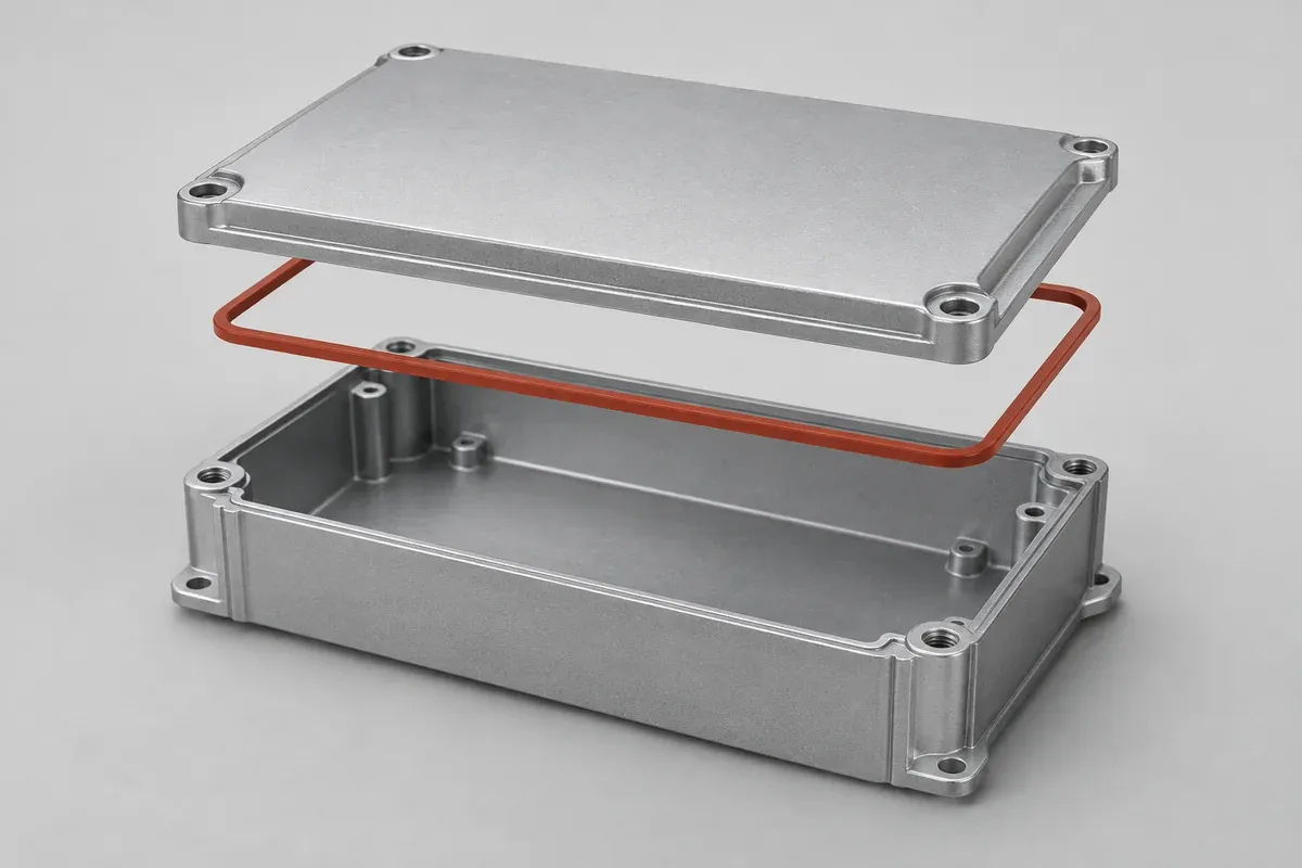
Consider a molded silicone perimeter gasket between a housing and removable lid. A groove locates the seal, and fasteners close the joint. The proposed design may include mechanical stops that limit closure. No pressure, ingress rating or life requirement is assigned to this example.
The review asks how the seal's free profile relates to the available space after the joint is closed. Material hardness alone cannot answer that question. Groove dimensions, seal geometry, lid and housing variation, fastening and local deformation all need to be represented.
Keep the required sealing path and mating-part revisions fixed while comparing concepts. If a larger bead or shallower groove is proposed, record which interfaces and assembly forces it may change. Increasing nominal squeeze is not, by itself, a complete sealing solution.
Closure concepts
Compare a controlled stop with an undefined closing condition.
Concept A relies on the fastening process to establish the final joint position without a separately defined hard-stop relationship. Concept B includes specified mechanical stops intended to control that position. These are review concepts; neither has demonstrated acceptable sealing or closure force.
For A, ask how assembly variation will be controlled and measured. For B, ask whether the stops actually establish the intended space around the entire perimeter. Local flexibility or a poorly supported region may still create a different condition between fasteners.
Also examine seal retention during assembly. A tab that helps locate the gasket should not create an unintended leak path or prevent the lid from reaching its intended position. Separate the locating task from the sealing task in the drawing and trial plan.
Tolerance relationships
Evaluate the perimeter, not only a convenient cross-section.
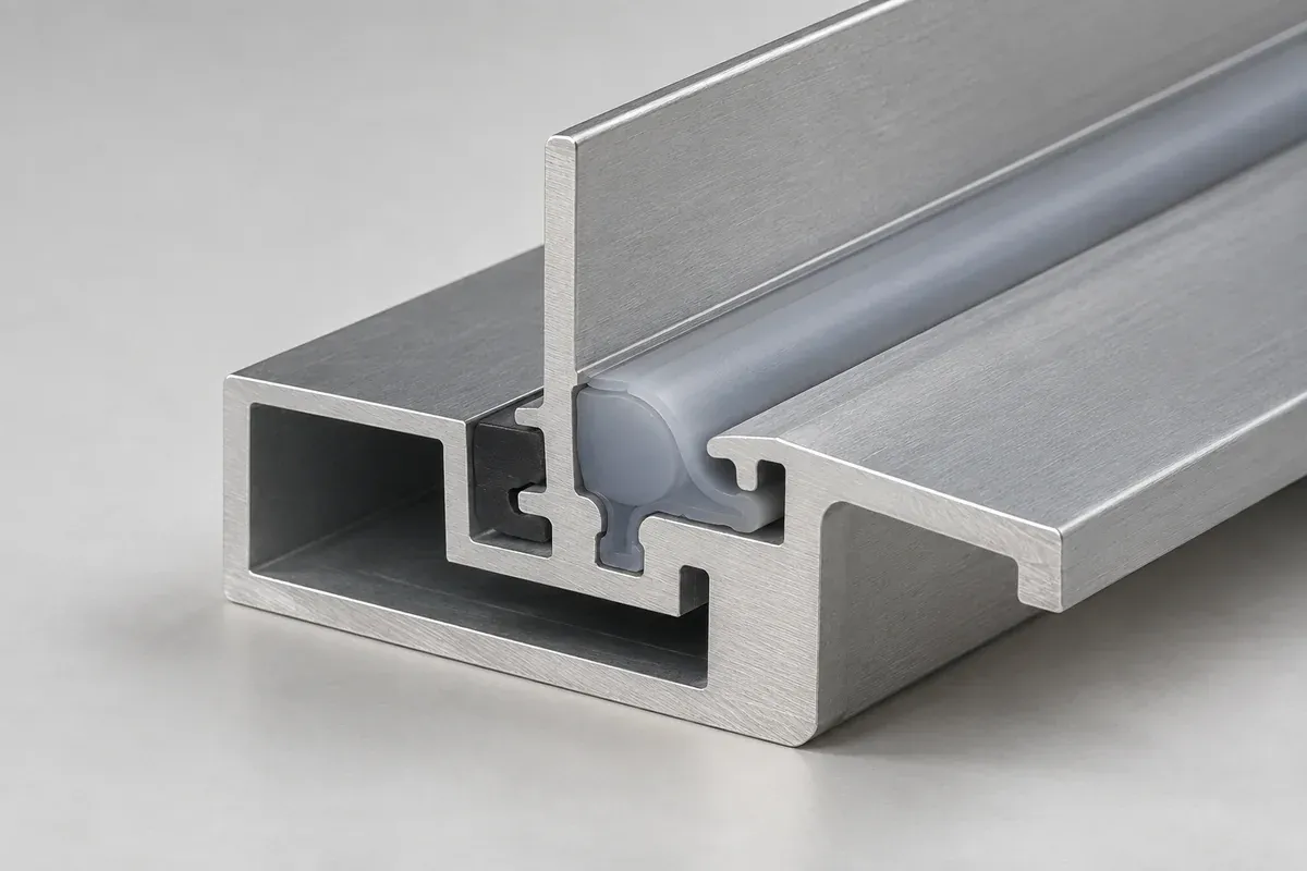
Review corners, transitions and regions near locating or fastening features. The same nominal profile can experience different local closure conditions when mating geometry changes. Identify which sections govern the design rather than inspecting only the easiest straight segment.
Define the state in which the flexible seal is measured. Excessive contact force or a fixture that stretches the gasket can distort the result. The component inspection method must represent the required feature without silently changing it.
| Area | Definition needed | Evidence to agree |
|---|---|---|
| Free seal | Profile, material, permitted flash and specimen condition. | Low-distortion component measurements and surface inspection. |
| Mating groove | Depth, width, local form and locating features. | Controlled mating-part inspection. |
| Closed joint | Stops, fasteners, sequence and local support. | Closure observations and the separately specified assembly sealing test. |
See the groove tolerance guide for the input structure. Any numerical design rule must come from the actual seal system and engineering evaluation, not from this illustrative table.
Proposed verification
Separate empty closure, component checks and sealing evaluation.
First inspect the housing and lid and observe their agreed empty closure condition where appropriate. Then inspect identified gasket samples for the specified profile and surface zones. Assemble the defined configuration, recording seal placement and the fastening method.
Evaluate whether the joint reaches its intended position without an unintended obstruction or displaced gasket. Preserve observations at corners and between fasteners. A visually closed seam is useful context but is not evidence that the joint satisfies a particular ingress or leakage requirement.
Perform any required sealing evaluation using the approved assembly test and conditions. If compression-set or repeated-opening behavior matters, scope it separately with the exact grade and use profile. Do not translate a generic material value into a promised service life for this joint.
Investigation plan
Separate a displaced seal from an incorrect closure definition.
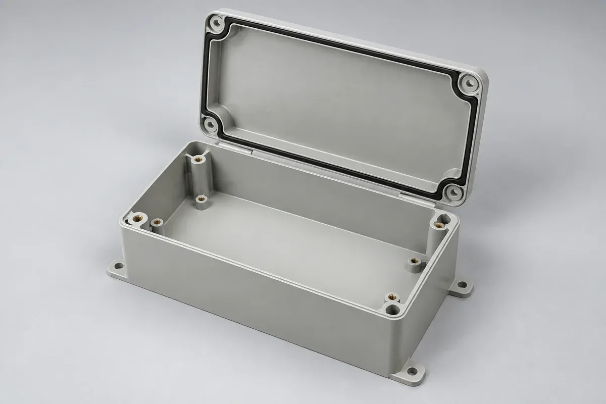
If the lid does not reach its intended position, inspect placement and interference before changing the seal hardness. A twisted corner, trapped locating tab or foreign material can produce a closure symptom that is unrelated to the selected formulation. Record the observed condition before disturbing the joint.
If a sealing evaluation fails, preserve the assembled configuration and follow the agreed investigation method. A failure location can guide inspection of the mating surfaces, groove and local seal condition, but it should not be presented as proof of a single cause without supporting evidence.
Compare an approved revision with the same mating hardware and assembly procedure where possible. Changing bead shape, fastener sequence and material at once can obscure the relationship being investigated. The purpose of a controlled comparison is to learn which configuration meets the defined requirement.
Any permitted rework, trimming or assembly aid belongs in the record and commercial scope. A hand-adjusted development gasket may help isolate a question, but it should not silently establish the production acceptance standard.
Approval boundary
Close the joint requirements before claiming performance.
A real development review could change the groove, seal profile, locating method, stop arrangement or material. Each revision needs a controlled comparison against the required closure and sealing behavior. The most visually substantial bead is not automatically the correct solution.
Assign responsibility for the mating hardware, seal specification, assembly procedure and complete-joint qualification. Include permitted flash and trimming requirements in the component order. Unresolved acceptance criteria should remain visible rather than becoming implied supplier guarantees.
The output is a clear link from free geometry to a defined closed condition and a proposed verification sequence. It does not establish an IP rating, chemical compatibility or measured improvement. The LSR gasket RFQ guide helps turn the resolved decisions into a quotation package.
Apply the review to your part
Turn your drawing into a defined review.
Send the seal, groove and closure arrangement with the intended exposure and required evaluation. Keep component acceptance separate from finished-joint performance.
Explore our custom lsr injection-molded gaskets and seals or the broader injection molding service.