
Illustrative engineering study · September 28, 2026
D-Shaft Control Knob: Fit and Angular Indexing Study
A knob can seat on a shaft and still indicate the wrong angular position.
The design question
What establishes the relationship between the pointer and the control?
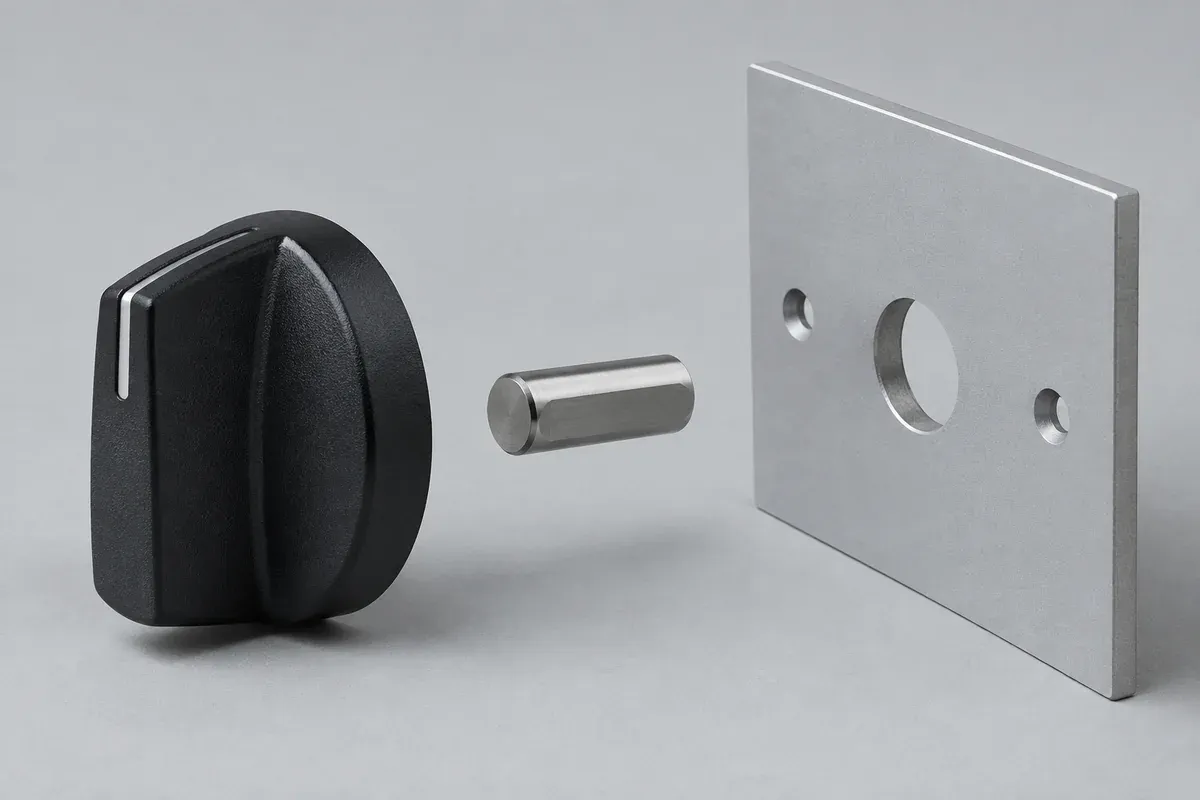
Consider a molded pointer knob on a D-shaped shaft protruding through a panel. The knob has an integral index feature and a defined seating position. The control mechanism and panel reference are supplied by the product designer. No torque, retention or angular tolerance is selected in this example.
The review asks how the shaft flat, knob bore and visible index share an angular reference. Nominal shaft diameter alone cannot answer that question. The control body's installed orientation also belongs in the relationship, even though it is not part of the molded component.
Keep the control, shaft and panel revisions fixed while comparing knob concepts. A rotated panel mark can hide a knob-interface issue without resolving it. Record any counterpart change explicitly before interpreting the assembled indication.
Reference comparison
Use the functional bore rather than an arbitrary cosmetic feature.
Concept A locates the visible mark using a cosmetic outside feature whose relationship to the bore is not fully specified. Concept B defines the mark from the functional D-bore reference. The comparison concerns drawing clarity and inspection, not a claim that either sample has been tested.
For A, ask how the tool, marking fixture or inspection method establishes angle. A circular skirt provides no unique angular reference by itself. For B, confirm that the reference can be used without distorting the part or relying on an uncontrolled witness.
If a secondary marking operation is proposed, carry the same functional reference into that process. A molded index and a printed line require different production controls, but both must indicate the intended state of the assembled control.
Assembly relationships
Separate angular fit, axial seating and panel clearance.
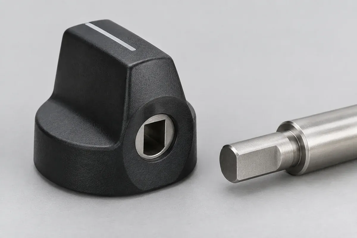
Define the full D-profile, engagement region and permitted movement. Then identify what establishes the final axial position. A knob that bottoms on an unintended shaft feature can appear secure while leaving an incorrect panel gap or insufficient engagement.
Check the skirt and surrounding controls through the required rotation range. Contact with the panel can create apparent turning resistance that is unrelated to torque transfer at the shaft. The acceptance plan should distinguish those effects.
| Relationship | Definition needed | Proposed check |
|---|---|---|
| Shaft to bore | D-profile, engagement, material and mounting method. | Controlled counterpart fit and dimensional inspection. |
| Bore to index | Angular reference and mark definition. | Component-level index-location check. |
| Assembly to panel | Control orientation, seating and rotation envelope. | Panel gap, indication and interference review. |
The shaft-interface guide provides the input structure. A drawing relationship does not replace the functional evidence required for the actual control.
Proposed sample sequence
Record the indication before and after the required checks.
Inspect identified knob samples and the controlled shaft configuration first. Assemble them using the defined method and support. Observe seating, panel clearance and index position before applying any functional test. Do not use forceful trial assembly to conceal an unresolved bore relationship.
Scope torque transfer and axial retention as separate checks with suitable fixtures and criteria. A knob can remain attached yet shift angularly, or preserve its index while failing a retention requirement. Record the specific observation rather than an ambiguous statement that the fit feels good.
Where the plan requires repeated use or environmental exposure, preserve specimen identities and inspect the relevant relationships afterward. A sample altered during an overload or removal trial should not be silently reused as an untouched production reference.
Investigation plan
Distinguish a marking problem from an interface problem.
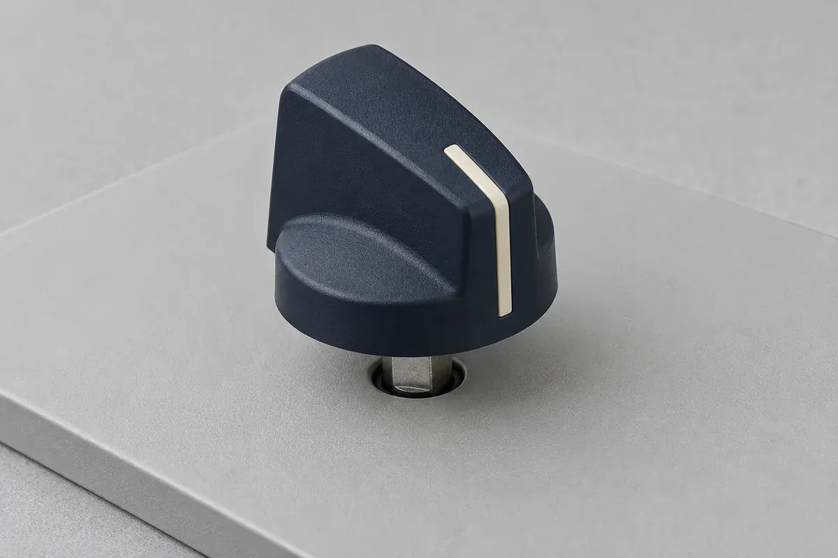
If the pointer appears misaligned, compare the component-level index relationship with the installed control orientation. A correctly made knob can indicate incorrectly when the control body or panel reference differs from the intended assembly. Repositioning the printed mark without checking those relationships may conceal the actual issue.
If the knob shifts during operation, record whether movement occurred at the shaft interface, within an insert joint or elsewhere in the control. A change in the visible index is an observation, not a complete diagnosis. Preserve the configuration before tightening or modifying anything.
For an axial seating concern, check the specified stop or engagement region and the panel clearance independently. An attractive flush appearance is not proof of correct shaft engagement, and extra installation force should not be used to compensate for an undefined seating requirement.
The next revision should identify the changed feature and retain the other controlled references. That approach lets the team evaluate a specific corrective concept without inventing an explanation or claiming that the illustrative assembly has already passed a functional test.
Decision boundary
Release the visible indication with the hidden joint.
A real development review could adjust the bore, engagement, index definition or mounting method. The selected option must satisfy the complete assembly requirements. This study does not claim that a D-shaped interface is always preferable to a spline or a specified round-shaft joint.
Assign ownership of the shaft drawing, control orientation, molding configuration, marking process and acceptance fixture. Record approved material and hardware choices. A later insert or resin substitution should follow the agreed change review.
The deliverable is an aligned drawing and evidence plan, not an invented torque rating or customer success story. See the index and texture guide and acceptance guide to turn the resolved relationships into a quote-ready package.
Apply the review to your part
Turn your drawing into a defined review.
Send the knob, shaft, control and panel references together. Define how seating and angular indication will be checked before approving production.
Explore our custom injection-molded control knobs or the broader injection molding service.