
Illustrative engineering study · September 28, 2026
Coil Bobbin Winding Space and Terminal Positioning Study
A usable winding envelope needs a clear relationship to wire exits, terminals and the assembly fixture.
The design question
Can the winding and terminal operations share a controlled reference?
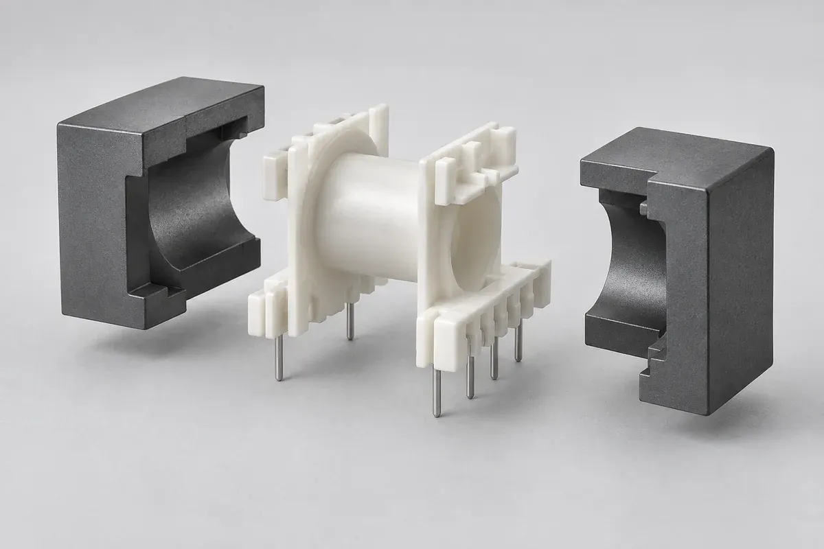
Consider a custom rectangular coil former with two flanges and a row of terminals. A winding nest supports the plastic part, leads pass through local slots, and the completed component later interfaces with a core and circuit board. The exact winding and electrical design are outside this illustrative molding study.
The question is whether the bobbin's references let those operations agree on position without forcing the component into different states. A nominal terminal pitch can be correct while the terminal row is incorrectly located relative to the winding nest or core passage.
Keep the selected core envelope, winding requirements and terminal drawing fixed during the initial comparison. Any later change belongs in a revised configuration. This prevents a larger flange or moved pin row from being treated as an unnoticed tooling convenience.
Locating concepts
Distinguish a convenient outer surface from an intended datum.
Concept A locates the bobbin using convenient outside flange surfaces. Concept B defines seating and locating features deliberately in relation to the core passage and terminal arrangement. Neither scheme is approved merely by naming it; both need geometry, fixture and process review.
For A, ask whether parting lines, gate witnesses or local form changes can affect seating. For B, examine whether the proposed references remain accessible during winding and inspection. Adding a precise-looking pad is not helpful if wire or hardware later prevents the fixture from contacting it.
Consider permitted assembly freedom as well. Over-constraining a thin flange can deform it, while insufficient location can leave an uncontrolled terminal relationship. The design engineer and winding owner need to resolve these choices together.
Interface review
Trace three relationships through the same component.
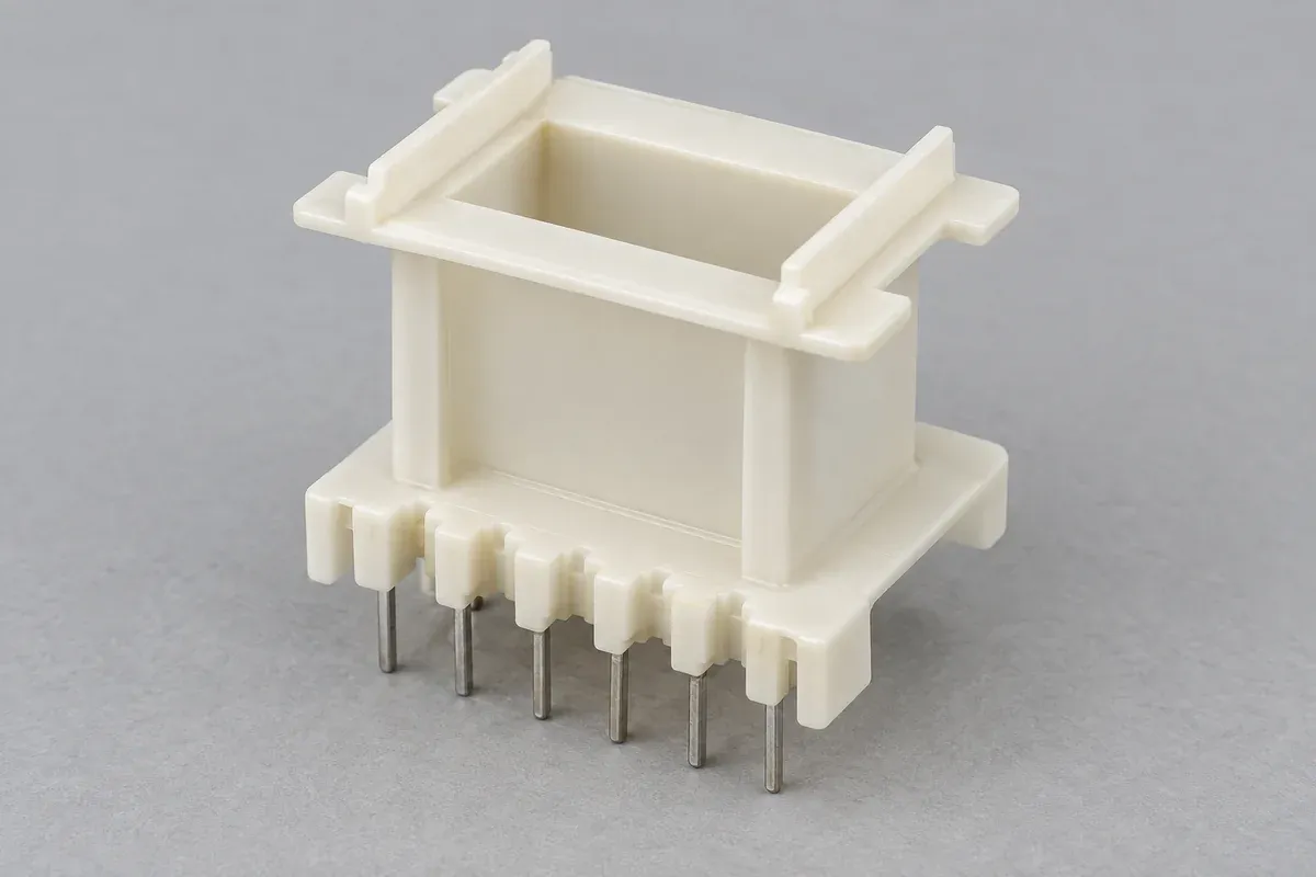
First relate the fixture references to the usable winding space. Then relate the lead route to the terminals. Finally relate the terminal row and core passage to their downstream counterparts. Each relationship needs the actual controlled component definitions rather than approximate visual alignment.
Review the wire-contact edges and the molding plan together. A witness in a noncritical outside region may be acceptable, while the same condition in a lead slot can require a specific restriction. The drawing should distinguish those zones.
| Relationship | Required definition | Proposed evidence |
|---|---|---|
| Nest to winding space | Seating references, flange form and winding envelope. | Empty-part inspection and representative fixture seating. |
| Lead slot to terminal | Routing motion, contact surfaces and pin arrangement. | Visual edge review and defined downstream trial. |
| Terminal and core interfaces | Counterpart drawings, datum relationship and specimen state. | Agreed measurements and representative assembly checks. |
The window and lead-slot guide develops the geometry questions. This study does not assign creepage, clearance, dielectric strength or thermal ratings.
Proposed verification
Inspect the empty former before adding process value.
Begin with identified empty samples and their material records. Inspect the defined passage, flange references and wire-contact features before terminal installation or winding obscures them. Where pins are molded in, include their position and exposed-surface condition at this stage.
If terminals are installed later, record the installation method and inspect the configuration afterward. Then perform the agreed winding-nest seating and lead-routing trial. Preserve the same specimen identities so a change observed after an operation can be traced to the relevant stage.
Keep component checks separate from electrical assembly qualification. A successful winding trial can provide evidence about access and handling, but it does not certify the finished transformer. Any required electrical or thermal evaluation must be assigned to the appropriate product owner.
Investigation plan
Separate molded position from downstream handling changes.
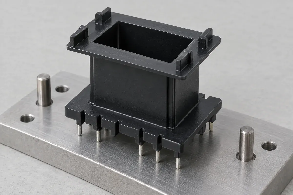
If terminals do not enter the intended counterpart, compare their position before and after the intervening operations. A molded or installed positional issue and a terminal bent during handling may produce the same final symptom, but they require different process corrections and responsibilities.
For wire-routing difficulty, inspect the actual path and the condition of the contact surfaces. An underspecified slot, an obstructing witness and an incorrect threading sequence are distinct possibilities. Preserve the original sample rather than immediately opening the slot with a hand tool.
A fixture change should be recorded with the part configuration. It may solve a process-access issue without changing the bobbin, or it may force the plastic into a state that conceals a dimensional problem. The review needs to distinguish these outcomes before interpreting a successful trial.
Agree which observations justify a drawing revision, a tool adjustment or a downstream-process correction. This prevents the plastic supplier from being asked to compensate silently for an uncontrolled counterpart and keeps the next quotation based on the actual approved delivery scope.
Release boundary
Approve the interface package and its responsibilities.
A real review could retain the initial references, revise local seating geometry or change the terminal installation route. Each option has tooling and process consequences. None of the alternatives here has demonstrated higher yield, faster winding or an approved electrical result.
Before tooling release, close material designation, counterpart revisions, fixture ownership, terminal supply and component acceptance. The material-record guide explains why resin recognition and finished-product approval should remain distinct.
The useful deliverable is a traceable sequence from the empty molded former to the agreed downstream interfaces. It supports a clearer quotation and trial plan without inventing performance data. The pre-winding inspection guide provides a practical starting point for that plan.
Apply the review to your part
Turn your drawing into a defined review.
Provide the bobbin, core, terminals and winding-fixture interfaces. Keep electrical design and finished-assembly qualification explicitly assigned outside the plastic component checks.
Explore our custom injection-molded coil bobbins or the broader injection molding service.