
PPS Impeller: Welding, Bore and Balance Review
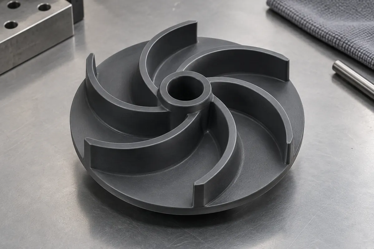
A small closed pump impeller required enclosed flow passages and a controlled shaft interface. The confirmed manufacturing route used separate molded sections, ultrasonic welding, bore finishing after welding and balance correction.
The project reached production supply with 8,000 pieces reported delivered by September 30, 2026. The case concentrates on the manufacturing and component-inspection record rather than assigning an unsupported complete-pump performance rating.
PPS + 40% GF
Project material specification
6.002–6.008 mm
Measured finished bore
8,000 pieces
Reported cumulative delivery
Project background
Component, scope and current phase
| Application | Closed impeller for a small water-pump assembly |
|---|---|
| Material | Celanese Fortron 1140L4 PPS-GF40, as identified in project records |
| Geometry | Nominal 60 mm outside diameter, 25 mm height and six curved blades |
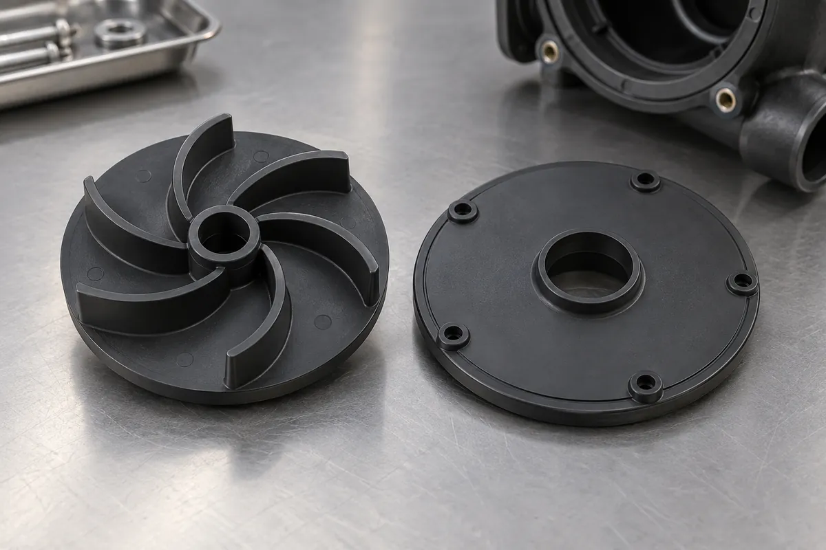
| Confirmed construction | Bladed rear section and front cover molded separately, then ultrasonically welded |
| Finished bore requirement | Ø6 H7: 6.000–6.012 mm |
| Current phase | Production supply; extended fluid-exposure evaluation still open |
Engineering challenge
What the development work needed to resolve
Early development identified rotating imbalance, excessive shaft-interface clearance and blade-region issues. Enclosed passages also required an explicit manufacturing route rather than an assumption that the impeller was molded as one closed piece.
The bore needed to be evaluated after joining because the delivered geometry includes the weld operation. Component runout and balancing were kept separate from complete-pump vibration and hydraulic performance.
Manufacturing review
Changes and the verification approach
The rear plate and blades were molded as one section, with the front cover produced in a separate tool using the same specified material. Locating and joining surfaces were then used for ultrasonic assembly. This owner-confirmed sequence supersedes the earlier incomplete process description.
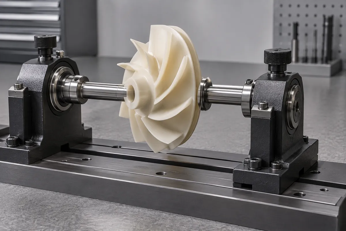
After welding, the shaft bore was reamed to the corrected H7 numerical limits. Balance correction followed in the defined finished configuration, avoiding a misleading claim based only on the geometry or mass distribution of a molded half.
The dimensional report and balance sample were recorded separately. The supplied balance summary indicates acceptance within the project G2.5 requirement at 1,000 rpm; this is not reported as a measured pump vibration amplitude.
T0 · May 10
50 pieces
T1 · June 1
200 pieces
Production · July 10 onward
8,000 cumulative pieces reported by September 30
Recorded observations
Results with their sample and test boundaries
Each result below applies to the stated specimens and configuration. Development, pilot and production checks are not combined into a single pass rate.
These are owner-supplied project summaries, not independently certified test reports.
| Check | Samples and conditions | Recorded observation | Interpretation boundary |
|---|---|---|---|
| Finished bore | July 15 production lot; 20 sampled impellers, after welding and reaming | 6.002–6.008 mm | Within the stated Ø6 H7 limits of 6.000–6.012 mm |
| End-face runout | Same 20-specimen dimensional sample | 0.010–0.018 mm | Against the project 0.02 mm limit |
| Balance evaluation | 50 sampled finished impellers; two-plane method at 1,000 rpm | Reported within the project G2.5 requirement | Sampled component balance, not complete-pump vibration or every-piece inspection |
| Outside diameter | 20 sampled impellers | 59.95–60.05 mm | Project dimensional result |
Release status
What is established and what remains open
Production supply was recorded, while a longer fluid-exposure program remained ongoing. No completed 500-hour hydrolysis qualification or universal service-temperature claim is made.
Pump flow and head are not promoted as product ratings here because the supplied summary does not establish the complete operating-point definition. Those conclusions belong to the identified pump assembly and its controlled test.
Published anonymously with the project owner's permission. Original test reports and project photographs were not supplied for this publication review. Images are product design illustrations; no customer or supplier identity is displayed.
Related guides
Plan the next component review
- Plastic Impeller Materials: PP, PA, PPS or PEEK?Compare PP, PA, PPS and PEEK for molded pump impellers using fluid exposure, operating temperature, blade geometry and shaft interfaces. Select exact grades.
- Open vs Closed Impellers: Molding and Assembly Trade-OffsCompare open and closed injection-molded impellers through flow-path access, mold release, welded construction and inspection. Do not assume closed passages are one-piece molded.
- Impeller-to-Shaft Connections: Press Fits, Inserts and KeywaysReview molded impeller shaft connections through torque transfer, retention, bore condition, inserts and assembly loads. Match inspection to the delivered state.
- Plastic Impeller Runout and Balance: Separate MeasurementsDistinguish impeller runout, rotor balance and pump vibration. Define mounting references, balancing speed, sample scope and correction before accepting a report.
- Thin Impeller Blades: Filling, Weld Lines and WarpageReview thin molded impeller blades for filling, cooling, weld regions, support and warpage. Preserve hydraulic geometry while making the design manufacturable.
- Validating a Molded Impeller in the Pump AssemblyValidate a molded impeller in its pump assembly with controlled configuration, operating points, fluid conditions and separate component acceptance records.
Review your component and its mating assembly
Send the drawings, operating conditions, quantities and acceptance methods to define tooling, molding and inspection.