
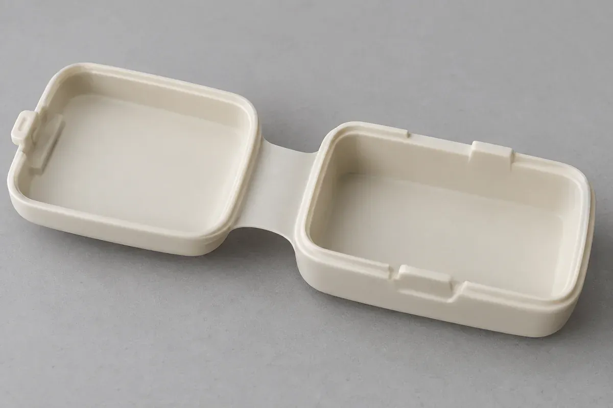
Product design illustrations. Final geometry, materials and acceptance criteria are project-specific.
An integral hinge can have a carefully drawn thin section and still need a serious molding review. The flow path into and through that section is part of the manufactured configuration. Gate placement should therefore be discussed before the hinge dimensions are treated as a complete design.
The aim is not to prescribe one gate position for every cover. It is to understand where material enters, how it reaches the flexible region and where flow fronts may meet. Those questions must remain connected to the actual part revision and selected resin.
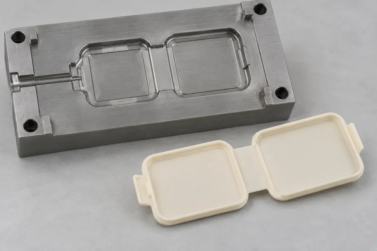
Review the flow path on the complete open part
Identify the proposed gate and follow the route through thick panels, narrow connections and the hinge. Check whether filling can become unbalanced across a broad span. A small isolated hinge sketch omits the surrounding geometry that influences how the cavity fills.
Protolabs' hinge guidance highlights gate placement and flow through the hinge. The application-specific question is whether the proposed tool arrangement supports the intended flexible region without an unacceptable meeting line or other defect there.
Ask for a drawing or model view of the gate, not only a statement that the part is moldable. If a simulation is provided, record the resin assumptions, geometry and process inputs used. A predicted fill pattern is useful evidence for planning, not a measured fatigue result.
Discuss meeting lines as functional locations
Flow can divide around features and meet again elsewhere. Identify whether the proposed meeting region intersects the flexure or another loaded feature. Do not evaluate it only by how visible the line appears under room lighting.
A line away from the hinge may still affect a latch or mounting feature. Conversely, a visible surface trace is not sufficient evidence to quantify a strength loss. Tie observations to the relevant functional requirement and obtain appropriate sample evidence.
If adding or moving a gate changes the flow, review the entire proposal again. The change can also affect gate witnesses, trimming, ejection and the appearance of connected panels. A local improvement should not be accepted without considering these consequences.
Protect the flexure during release and handling
Mark where ejector contact is permitted and which surfaces are critical to the bending region. Review the force path during release so that a thin hinge is not asked to carry an unsuitable load while a thicker panel remains attached to the tool.
Any planned first-fold operation belongs in the process record. Define its purpose, method and timing with the material and tool proposal. Do not improvise a warming or bending routine on selected samples and then claim that untouched production parts have the same configuration.
Investigate early cracking without guessing the cause
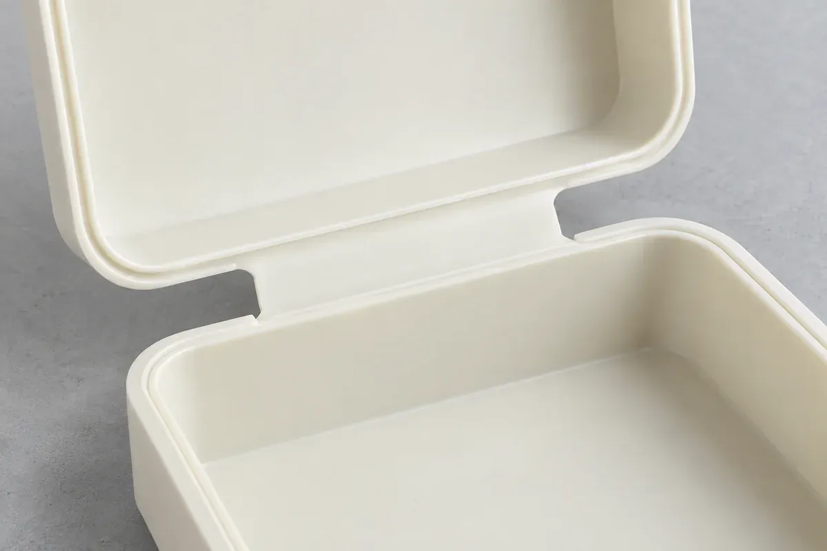
Preserve sample identity and document when cracking appears: release, first fold, assembly or later cycling. Inspect the location relative to the gate, hinge transition and any visible meeting line. Several mechanisms can create an early failure, so appearance alone should not settle the diagnosis.
Compare material identity and specimen history before attributing a difference to gate location. A resin substitution, changed folding method or a manually modified web creates another variable. Record these differences instead of merging all samples into one apparent pass/fail result.
Use the geometry guide to review web and transition questions. The material guide addresses exact-grade selection. These are complementary checks, not competing explanations chosen from a photograph.
Close the tooling decision with representative samples
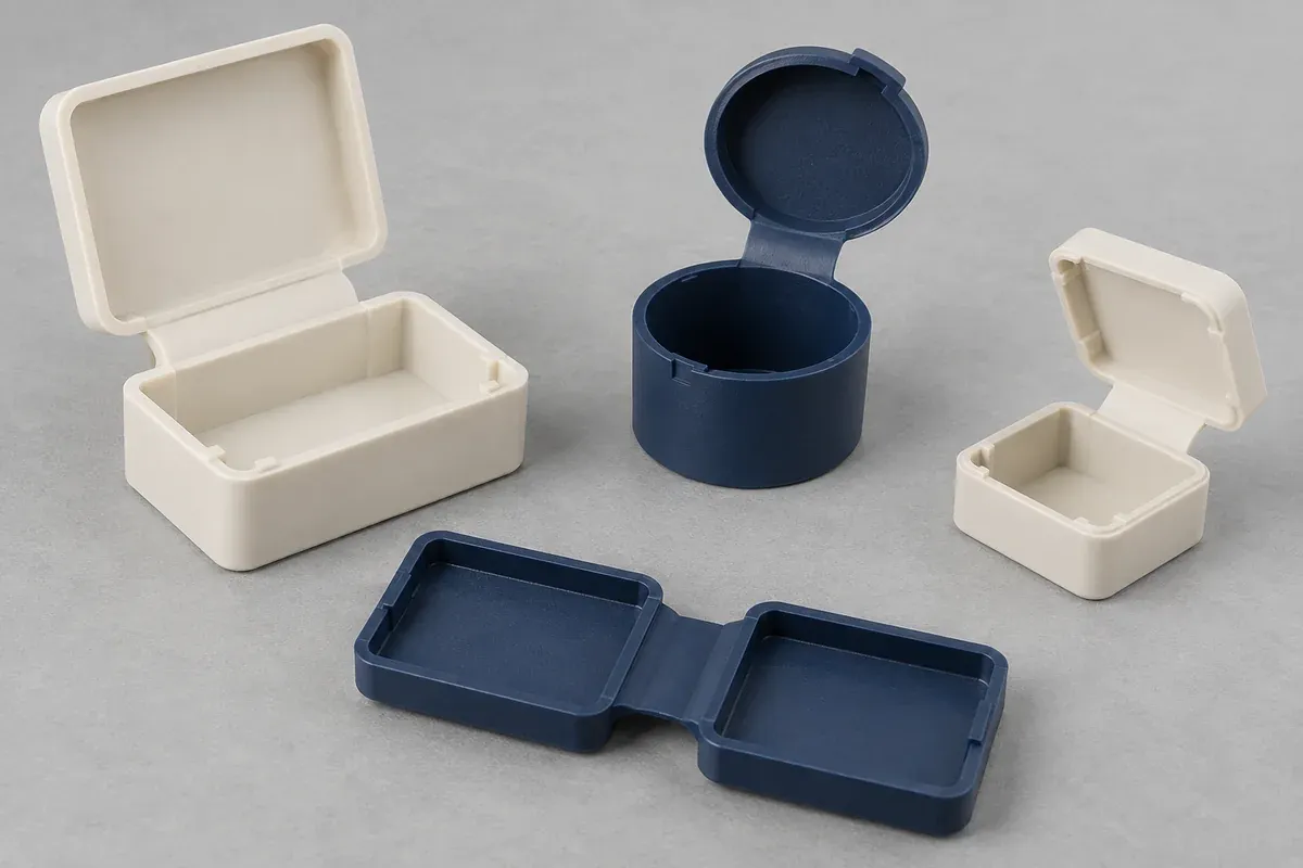
Agree the trial objective and relevant sample coverage before molding. Inspect the critical geometry and evaluate opening under the planned method. If a gate revision is made, distinguish the original and revised sample sets and repeat the checks affected by the change.
Keep the final gate, material and process assumptions with the approval record. A later change that affects filling through the hinge may require renewed review even if the nominal part drawing is unchanged.
The result should be a traceable connection between the tool proposal and demonstrated sample behavior. Avoid promising unlimited hinge life from a favorable flow picture; the cycle-test plan is where repeated-use requirements are evaluated.
Turn the review into a defined molding scope
Explore our custom injection-molded living-hinge parts and the related illustrative engineering study. Send the drawing revision, counterpart details, intended use and the decisions still open. Development samples and production approval should have separate, agreed deliverables.