
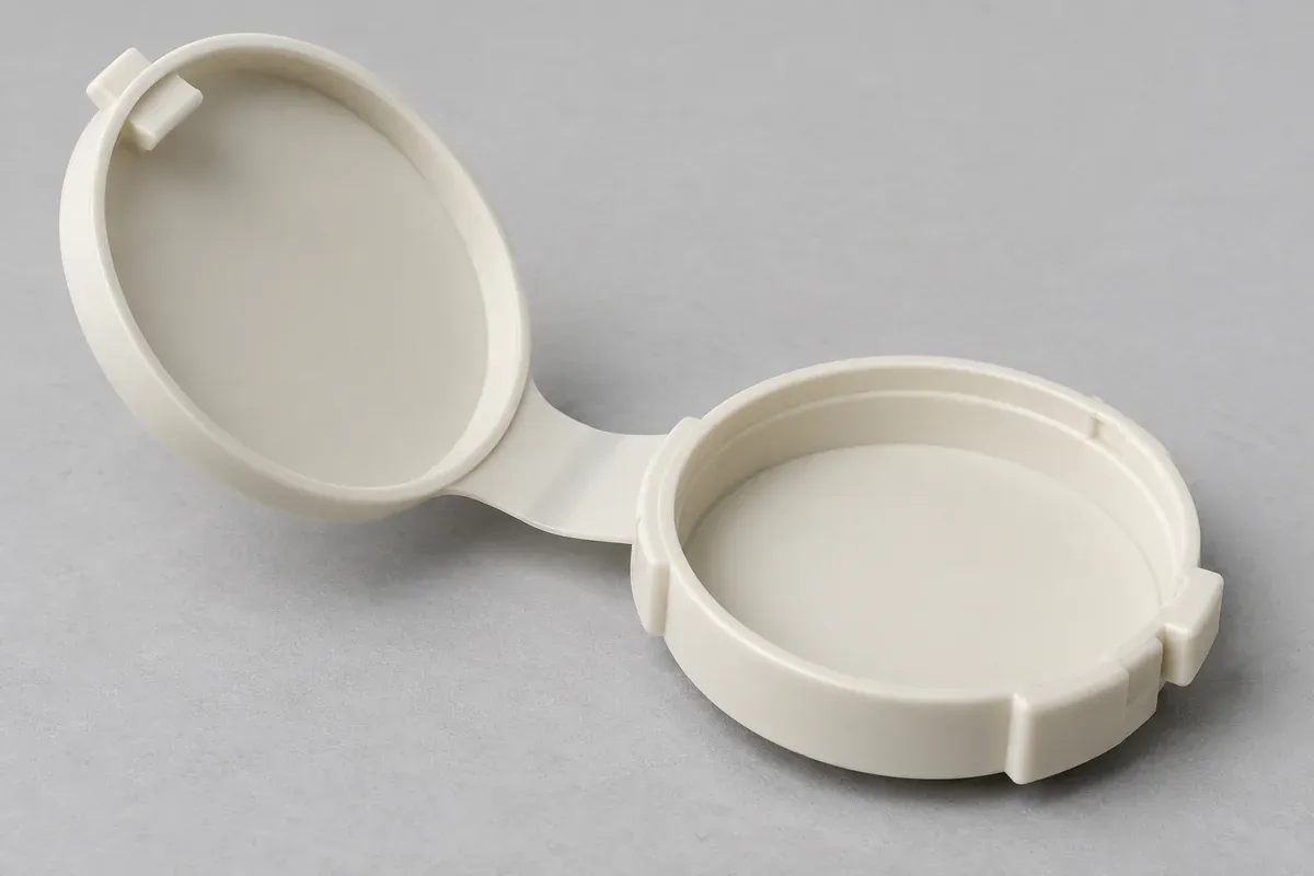
Product design illustrations. Final geometry, materials and acceptance criteria are project-specific.
A living hinge is not defined by one thin-wall dimension. Its web, transition regions, span and connected panels determine where the part bends as the cover moves. Copying a thickness from a familiar example can miss the actual bending path of a different mechanism.
Start with a section through the intended flexure and a view of the complete open part. Identify the material, opening direction and required positions. The purpose of the review is to make the geometry understandable before it becomes a fixed mold cavity.
Locate the region intended to bend
Mark the flexible web and the thicker adjoining structure. Ask whether the motion will concentrate in the intended region or force another thin feature to flex. A narrow rib, a nearby notch or an abrupt change in thickness can create a second bending location.
Check the opening motion with the connected panels present. A hinge coupon can help investigate a local geometry, but it does not include the same frame stiffness or interference as the finished cover. Keep coupon conclusions separate from complete-part conclusions.
Protolabs discusses thickness and bend radius as interacting hinge-design factors. Its examples are starting guidance, not a universal released dimension for every resin, span or opening requirement.
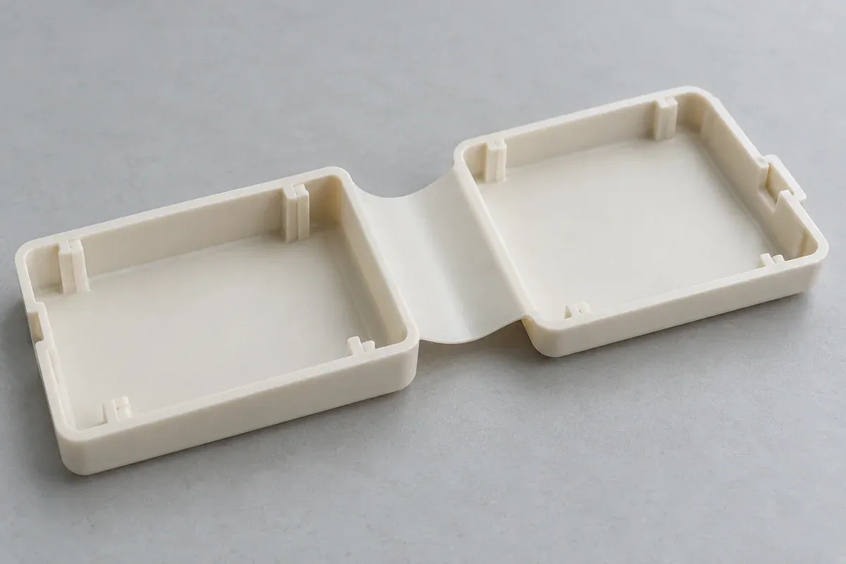
Review transitions on both sides
Follow each surface from the thin web into the thicker panel. Define intended radii and avoid leaving sharp transitions to interpretation. The inside and outside of the fold perform different geometric roles during motion; review both rather than annotating only the easiest view.
Consider adjacent molding features. A gate witness, ejector contact, logo recess or texture boundary near the flexure may need a restriction. Treat the critical region as a functional surface zone rather than only a cosmetic area.
The gate and weld-line review connects these drawing zones to the tool proposal. A smooth nominal section does not establish how the material will fill or how the part will be released.
Keep span and panel stiffness in the comparison
A long hinge joining a broad cover may respond differently from a short test strip. Check whether the cover can twist during opening and whether the intended support prevents unwanted loading. If two separated hinge webs are proposed, review how they share the motion.
Define where the user or mechanism applies force. Pulling at one corner is not the same condition as a centered fixture moving a rigid cover. Include the relevant use pattern in the validation plan rather than testing only the most convenient motion.
Do not assume that a thicker web always improves durability. Thickness changes flexibility, required motion and molding behavior together. Evaluate a proposed change with the exact material and mechanism instead of treating it as an isolated strength increase.
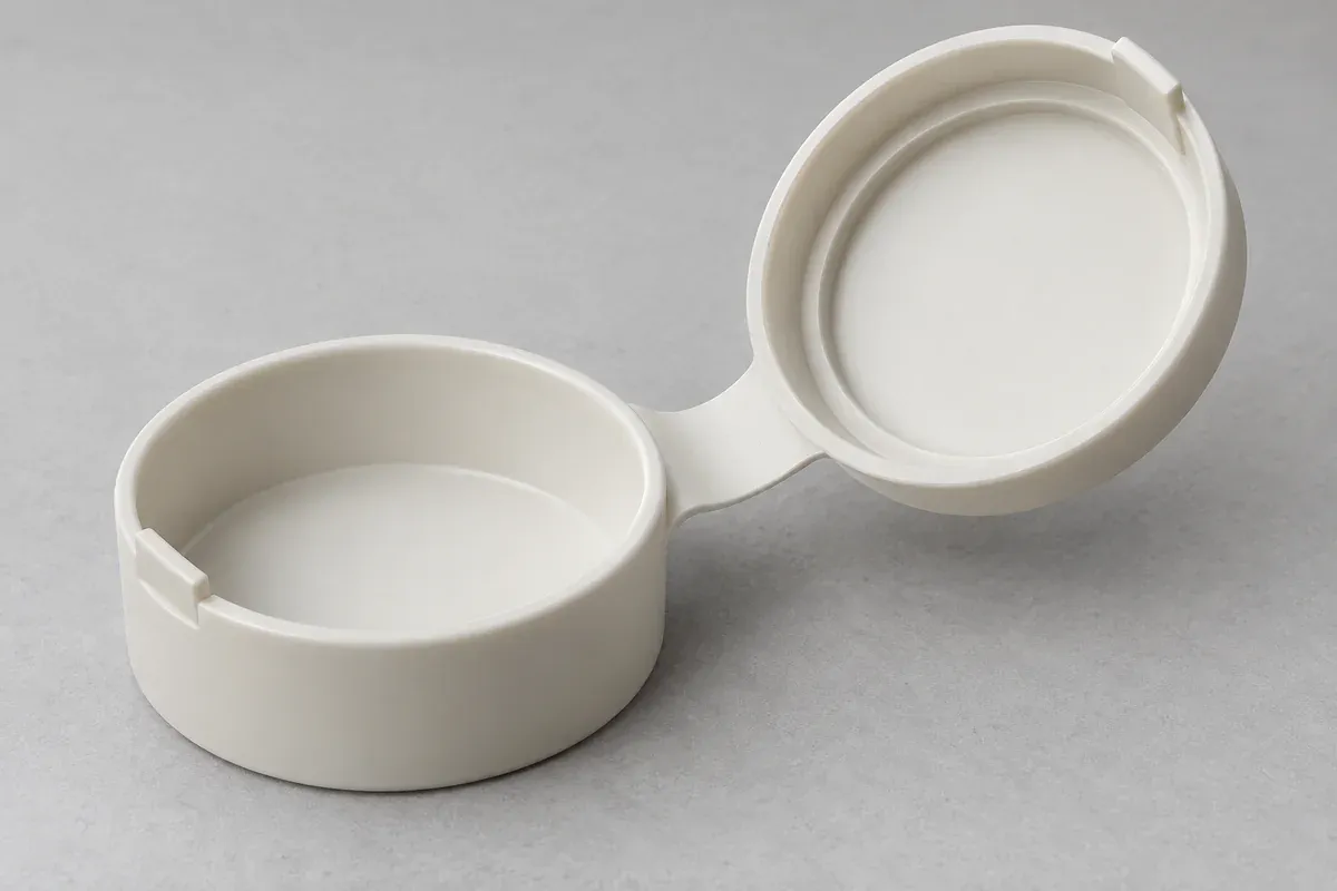
Define what can change during DFM
Separate fixed interfaces from development dimensions. The frame mounting, closed cover position and access envelope may be constrained, while local hinge details remain open. A clear change boundary lets the tool designer propose options without silently altering a required interface.
Ask proposed alternatives to show their effect on the open and closed positions, parting arrangement and release. A modification that improves filling but prevents the cover from reaching its required position is not a complete solution.
Specify how critical dimensions will be inspected on a compliant part. Support and restraint should represent the intended measurement state. A fixture that forces the web into shape can hide a condition that matters during actual movement.
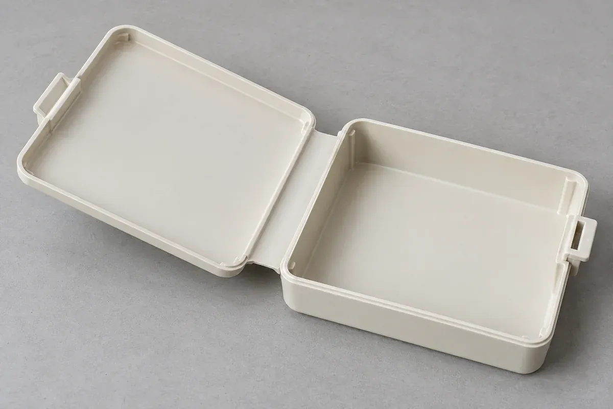
Validate geometry through staged evidence
Use early prototypes for access and motion questions, then representative molded samples for the material-and-process configuration. The prototype comparison explains why those stages do not provide identical evidence.
Record drawing revision, material and the sample's folding history. Define the opening range and criteria before a repeated-use test. If a geometry is revised, repeat the checks affected by the revision rather than assigning the previous result to a new web.
A finished review should leave a controlled section, a clear motion requirement and an inspection plan. It should not leave a single copied thickness carrying responsibility for the life of the entire mechanism.
Turn the review into a defined molding scope
Explore our custom injection-molded living-hinge parts and the related illustrative engineering study. Send the drawing revision, counterpart details, intended use and the decisions still open. Development samples and production approval should have separate, agreed deliverables.