
Illustrative engineering study · September 28, 2026
Dual-LED Light Pipes: Isolation and Alignment Design Study
An unwanted glow at the neighboring indicator can be an assembly-path question as well as a clear-part question.
The design question
How should two adjacent indicators remain distinguishable?
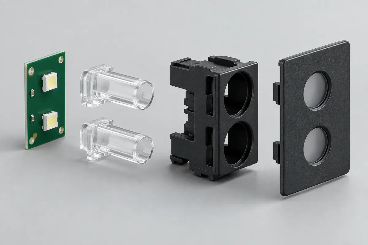
Consider a compact controller with two board-mounted LEDs and two visible panel indicators. Each LED has a separate clear molded guide. The PCB and panel belong to different assembly references, and an opaque carrier is available as a design option. No gap, resin or optical acceptance limit has been selected in this example.
The review asks two questions: how each entrance remains aligned with its LED, and how light from one channel is prevented from creating an unintended indication in the other. Increasing brightness does not necessarily resolve either issue. A brighter source can make an unwanted path more visible.
Keep the LED package, electrical drive conditions and panel arrangement fixed while comparing concepts. A change to those inputs should be recorded as a separate configuration. Otherwise a visible improvement cannot be attributed reliably to the revised guide or carrier.
Concept comparison
Separate clear guides alone or guides within opaque wells?
Concept A uses two independently mounted clear guides with open space around their entrances. Concept B adds an opaque carrier with separate wells around the entry regions. The carrier also provides defined locating features. These are review alternatives, not an assertion that either arrangement has passed an optical test.
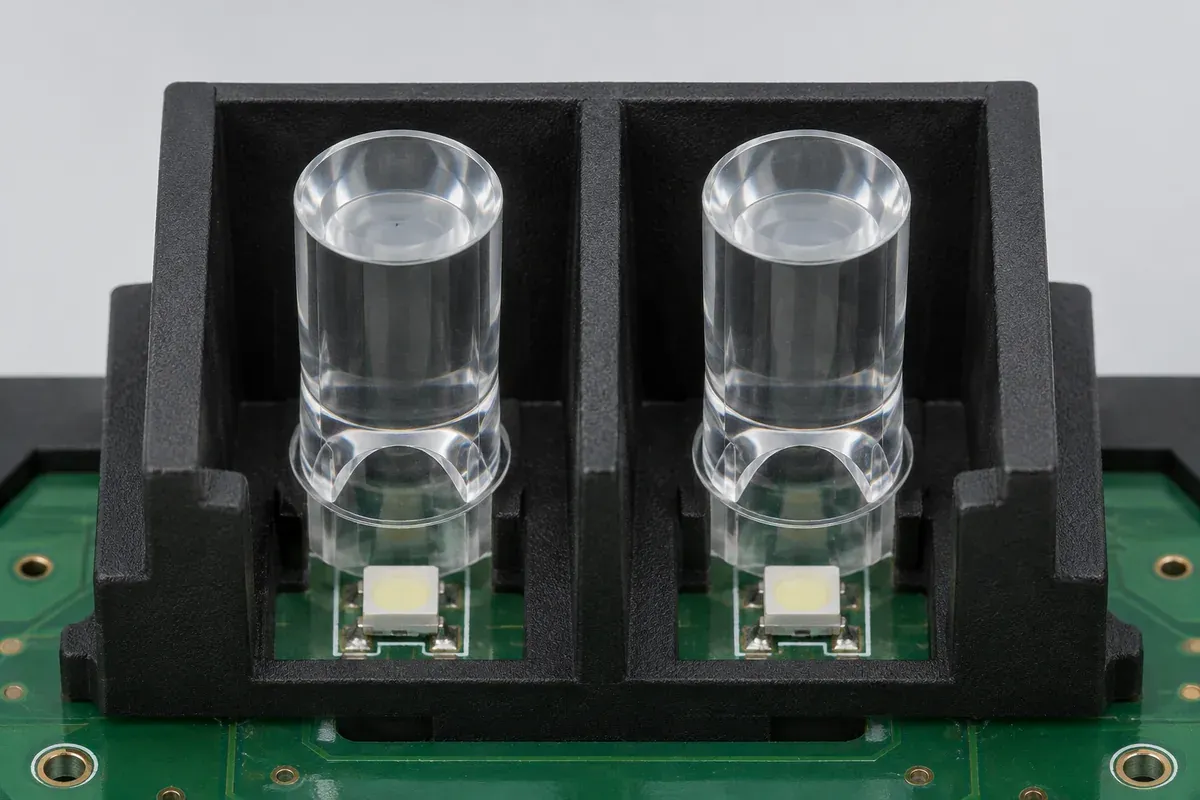
For A, inspect possible paths around the clear parts and through surrounding reflective or transmitting surfaces. For B, examine whether the wells actually separate the relevant paths without obstructing the intended LED-to-guide relationship. An opaque wall is useful only when its geometry addresses the path under investigation.
Compare assembly access and tolerance as well. Adding a carrier creates additional references and interfaces. It may improve definition of location, but can also introduce interference or stack-up questions if the PCB and panel are constrained independently.
Reference relationships
Follow both paths from the board to the visible face.
Trace the LED's position from the board reference and the guide entrance from its mounting reference. Compare those relationships in the assembled condition. Repeat the exercise for the exit face and panel opening. A correct exit appearance does not prove a correct entrance gap.
Identify permitted movement rather than assuming all parts are rigidly fixed. If one interface floats, specify where and how much within the approved design. Do not rely on flexing a clear part during assembly to reconcile incompatible references.
| Relationship | Inputs | Proposed check |
|---|---|---|
| LED to entrance | LED package, position, guide mounting and gap definition. | Datum-based inspection plus the controlled illuminated assembly. |
| Channel to channel | Guide spacing, carrier walls and nearby surfaces. | One channel active at a time under agreed viewing conditions. |
| Exit to panel | Opening, visible face and mounting freedom. | Assembly clearance and visible alignment check. |
The gap and offset guide explains why these inputs should be controlled together. The table organizes evidence; it does not assign optical tolerances or predict intensity.
Proposed sample sequence
Change the channel state without changing the observation setup.
Inspect identified clear parts and carriers first, recording surface condition and relevant dimensions. Assemble them with the controlled board and panel configuration. Establish the viewing angle, ambient lighting and drive conditions before comparing illuminated states.
Observe each channel separately, then the required combined states. Record which features and regions are evaluated, with a suitable agreed method for the acceptance question. A photograph taken with automatic exposure can assist documentation but should not silently become a calibrated brightness measurement.
If the neighboring face appears illuminated, preserve the initial setup and investigate the plausible path. Compare a documented carrier revision or surface condition without changing unrelated inputs. Keep unsuccessful observations as well as promising ones so the next decision is evidence-based.
Investigation plan
Distinguish an alignment issue from an unwanted light path.
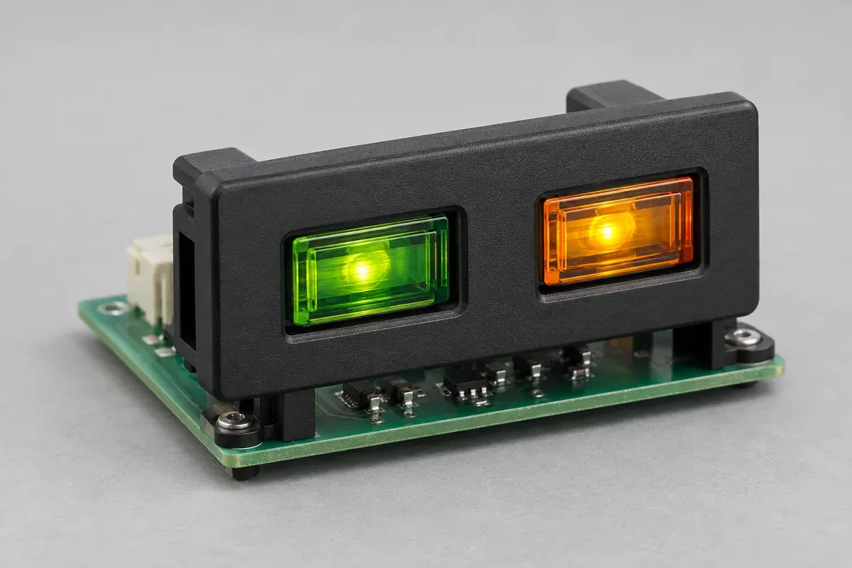
If one intended face is dim, inspect its entrance relationship and surface condition before assuming that isolation is the cause. If the inactive face glows, inspect possible paths around the guides as well as through them. The two observations may have different causes and should remain separate in the record.
A useful investigation compares one documented variable at a time where practical. For example, a carrier revision can be evaluated with the same clear guides and LED configuration. Replacing the LED, resin and carrier together may answer a final assembly question but makes the contribution of each change unclear.
Record both the illuminated and unilluminated appearance. A face that looks acceptable when bright may show an objectionable witness or inconsistent texture when off. Decide which states belong to the requirement instead of allowing the inspection method to select only the most favorable view.
Before changing tooling, identify which observation the revision is intended to resolve and which existing requirements it must preserve. This makes the next sample review a test of a specific proposal rather than an open-ended search for a pleasing photograph.
Decision boundary
Release a configuration, not a visual promise.
A real review might retain separate guides, add a carrier, revise a locating interface or change the optical geometry. The decision depends on the identified sample evidence and the required assembly behavior. Neither concept here has demonstrated a quantified improvement.
Before tooling release, assign ownership of the LED definition, material choice, critical surfaces, locating scheme and optical acceptance method. Agree which changes require another evaluation. A new LED package or resin grade should not be treated as equivalent solely because it fits the same outline.
The deliverable from this study is a connected review plan: references establish location, geometry defines possible paths, and a repeatable setup evaluates the required indication. See the sample acceptance guide for a fuller discussion of the evidence package.
Apply the review to your part
Turn your drawing into a defined review.
Send the LEDs, board, panel and guide models with the indicator states you need to distinguish. Keep proposed isolation changes separate from verified optical results.
Explore our custom injection-molded led light pipes or the broader injection molding service.