
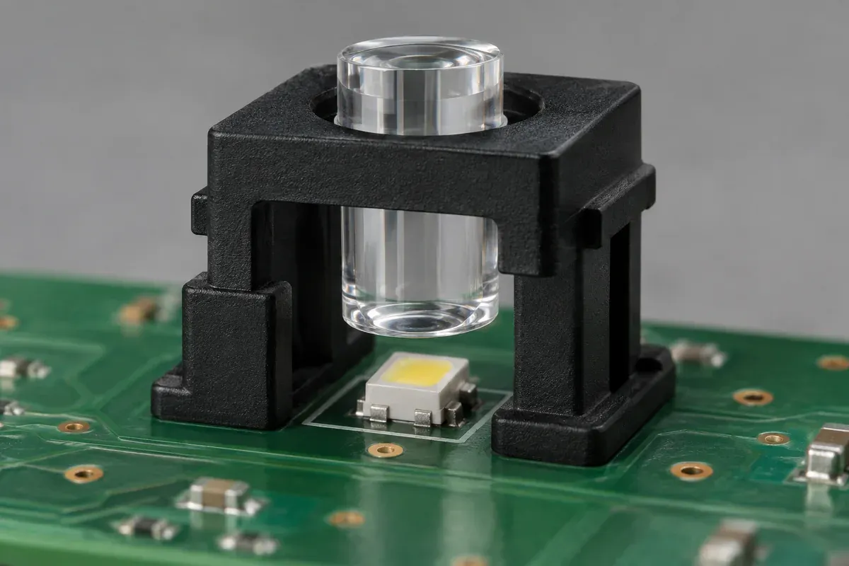
An indicator works with a hand-held light pipe but becomes dim or inconsistent when the enclosure is assembled. Moving the guide slightly restores the appearance. That observation suggests a coupling or locating issue, but it does not yet identify which dimension to change. The LED, board, guide and panel may all contribute.
Review gap, sideways offset and angular alignment as separate variables connected by the assembly references. A nominal distance in CAD does not describe the full range of positions after molding and installation. The objective is to define a workable optical and mechanical relationship, not to find the smallest possible nominal gap.
Product design illustrations. Final geometry, materials and acceptance criteria are project-specific.
Describe the entrance and source before assigning a distance
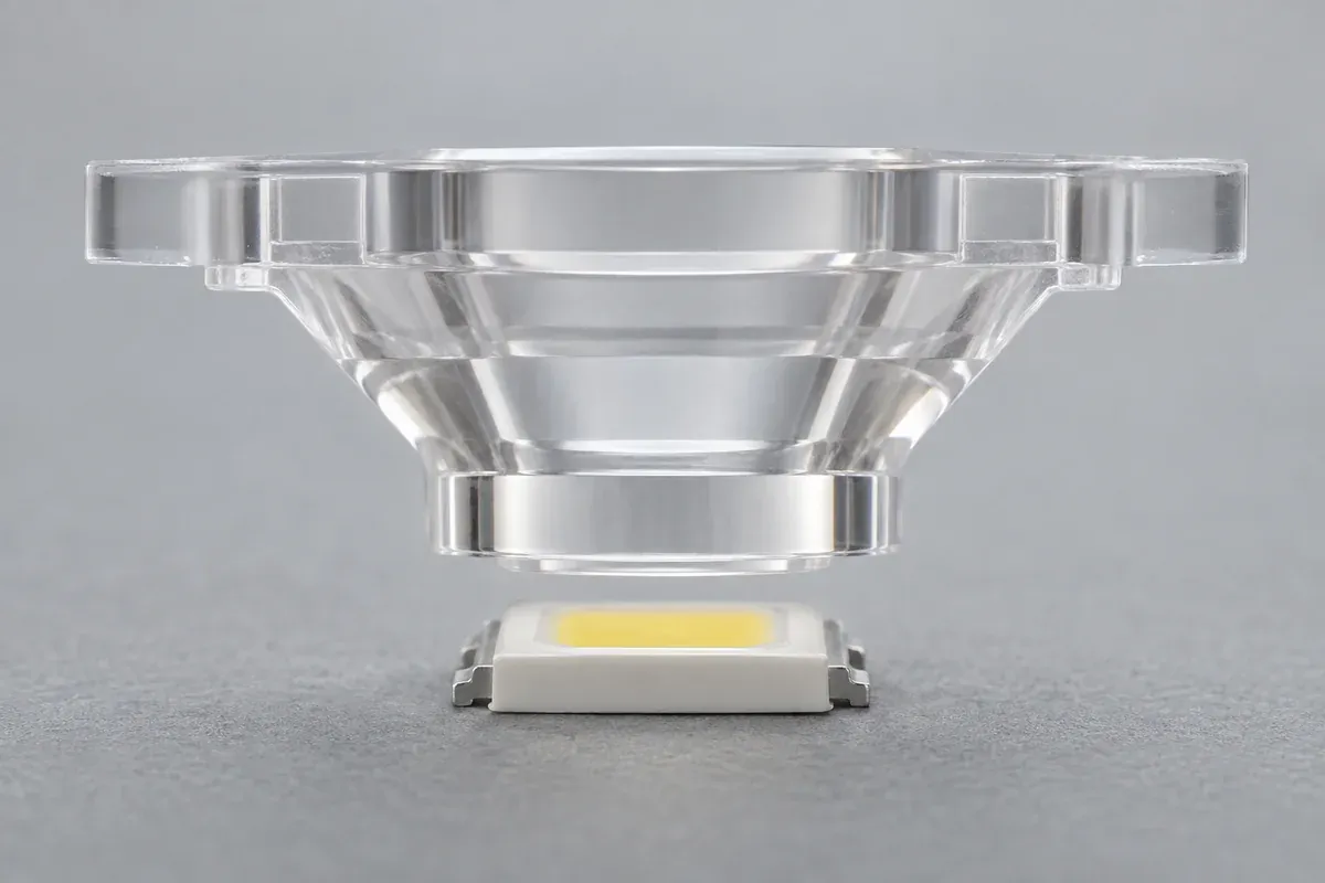
Obtain the controlled LED package drawing and the manufacturer's relevant optical information. Identify the emitting region, package form and angular distribution rather than treating the entire package outline as a uniform light source. Confirm the light-pipe entrance geometry and the intended orientation relative to that source.
Bivar's illumination handbook discusses matching the entrance to the source and preserving separation from the LED. Its guidance is a starting reference, not a universal production clearance for every custom part. Select the actual relationship using the component data, assembly variation and validation requirements.
Be careful with LED viewing-angle information. A quoted angular value commonly describes an intensity condition, not a hard boundary beyond which no light exists. It should not be used as though it creates a perfectly sharp geometric cone that proves how much light a guide will capture.
Trace two positions back to an agreed reference
Follow one path from the board or assembly datum to the LED's relevant location. Follow the second to the light-pipe entrance. If the guide is panel-mounted, that second path includes the board-to-panel relationship; if board-mounted, it includes its locating and seating features. Compare the two paths rather than listing isolated tolerances.
Include source placement, board location, guide geometry and available mounting freedom where they apply. Determine which dimensions are controlled independently and which share a reference. Adding every tolerance indiscriminately can be as misleading as ignoring the board and assuming the molded part alone controls alignment.
At this stage, distinguish an uncertain input from a permitted variation. A missing LED package revision is not a tolerance to put into a calculation. Resolve the configuration first, then choose an analysis method appropriate to the actual drawings and evidence.
| Variable | Mechanical contributors | Question for evaluation |
|---|---|---|
| Entrance gap | Source height, guide seating, board-to-panel spacing and local deflection. | Does the full range preserve clearance and acceptable indication? |
| Lateral offset | LED placement, locating features, aperture position and assembly freedom. | Can a valid assembled position move the source toward an entrance edge? |
| Tilt | Uneven supports, angular references, panel restraint or installation load. | Does the guide orientation change even when one point is correctly located? |
| Installation motion | Panel approach, board insertion and retention engagement. | Can the guide strike the package before reaching its final position? |
Do not use contact to make the stack disappear
Letting the guide rest on the LED may appear to remove a dimensional uncertainty, but it transfers a mechanical load to a component that was not necessarily designed for that role. Use intended support or stop features to establish the position. Check the LED manufacturer's restrictions on contact and loading.
Review the nearest possible approach under the defined assembly conditions. This may differ from the nominal gap because a board bows, a panel moves or a retention feature seats differently. Conversely, increasing the gap without examining optical coupling can solve a contact problem while creating a visibility problem.
Make the comparison reveal the variable being changed
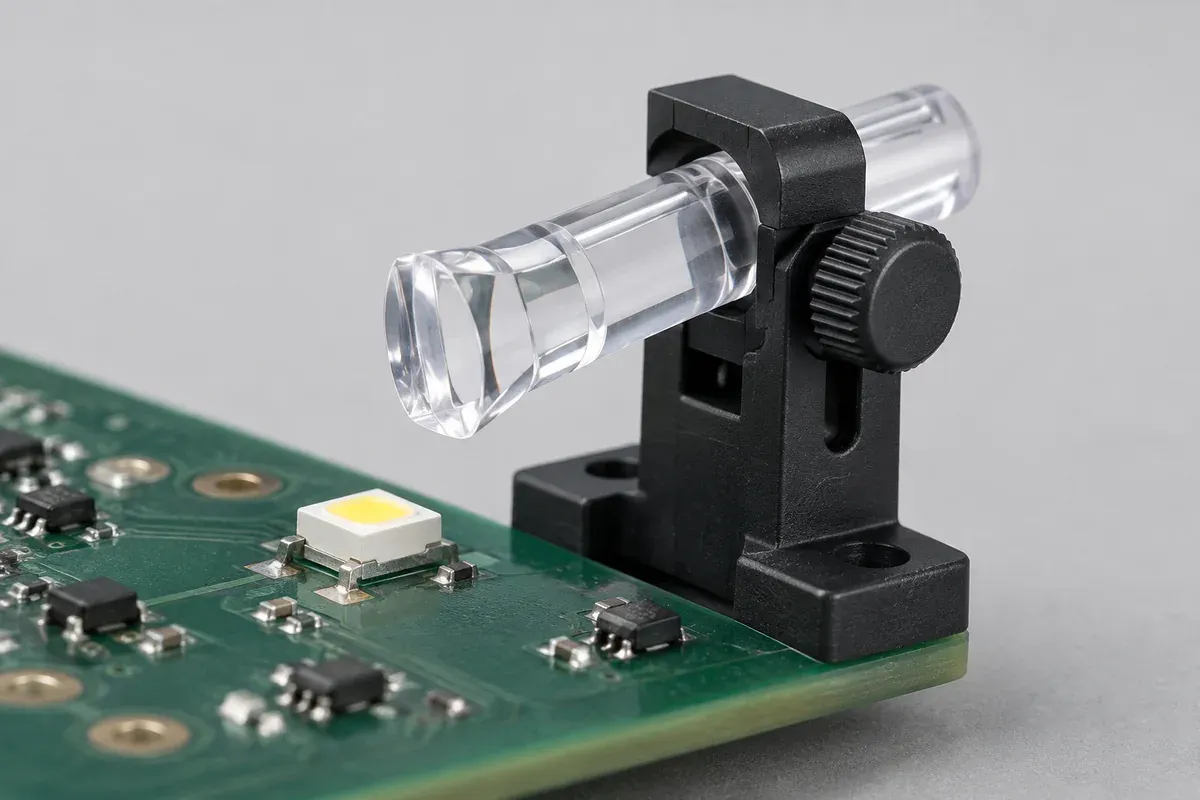
For development, hold the LED type, drive condition, guide specimen and viewing setup constant while investigating one alignment variable. Record the positions used and avoid forcing a part into a location it cannot occupy in the production assembly. A temporary adjustable fixture can support investigation without becoming a production acceptance fixture.
If several conditions change together, describe the result as a configuration comparison rather than evidence about gap alone. Replacing the LED, polishing a surface and moving the guide at the same time does not isolate which change affected the indication.
Optical modeling can help investigate the proposed configuration when appropriate inputs and expertise are available. Do not present a simple CAD rendering as ray tracing, or treat a nominal simulation as proof of performance across manufacturing variation. Keep predicted behavior distinguishable from measurements on identified specimens.
Close the loop with the assembled viewing requirement
Evaluate the output where the user sees it, with the panel and any intended masks or bezels installed. A guide that captures light well can still produce an unsuitable exit appearance. Conversely, an attractive unmasked bench result can hide leakage that becomes visible through a nearby opening.
Check the relevant single-indicator and adjacent-indicator states using the agreed method. Our crosstalk review addresses unintended paths, while the acceptance guide defines the observation conditions needed for useful comparisons.
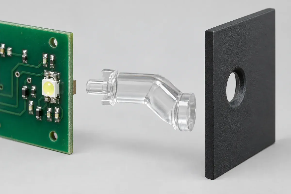
A successful alignment review ends with controlled references, an agreed range of conditions and evidence tied to the same configuration. It may lead to revised supports, an entrance change, a different mounting scheme or a board-layout discussion. The useful deliverable is a justified design decision, not a universal gap copied into every future drawing.
Turn the review into a defined molding scope
Explore our custom injection-molded LED light pipes and the related illustrative engineering study. Send the drawing revision, counterpart details, intended use and the decisions still open. Development samples and production approval should have separate, agreed deliverables.