
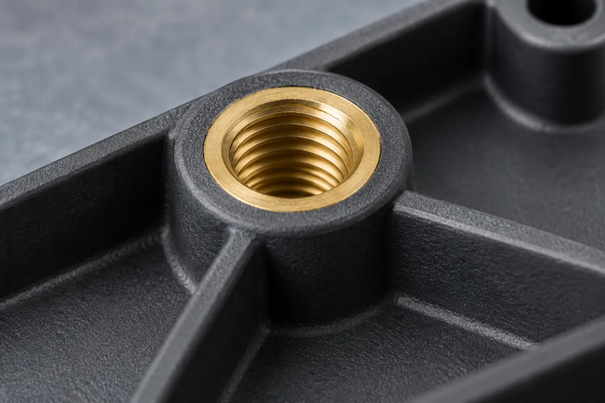
The bracket looks finished, but the assembly screw stops before the mating faces meet. It is tempting to classify the problem as “plastic in the thread” and send the batch for cleaning. That diagnosis may be correct, but a wrong thread, damaged entry, insufficient usable depth or an oversized screw can produce a similar complaint.
Define what “clear thread” means before choosing an inspection or repair. An insert-molded part needs the specified thread form and usable engagement, not merely a bright opening in a photograph. This guide connects the thread requirement in an RFQ to tooling review, incoming hardware and finished-part inspection.
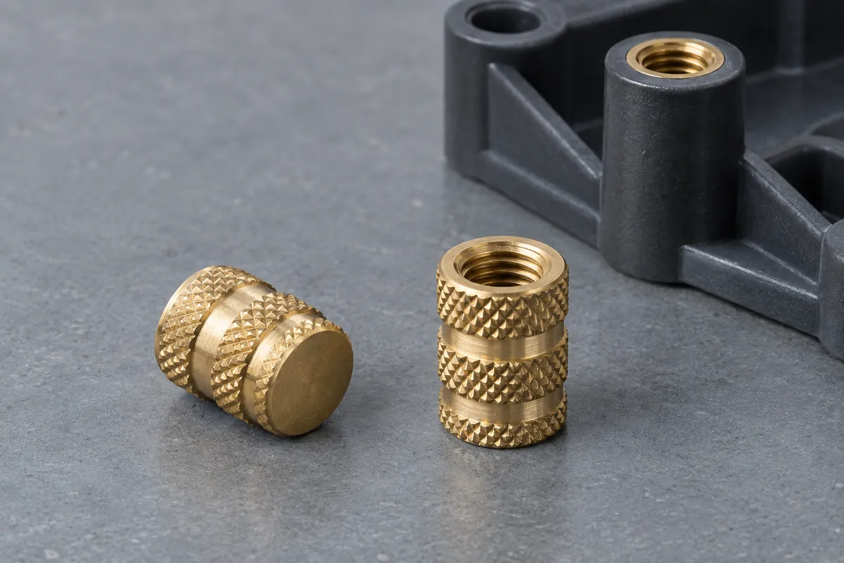
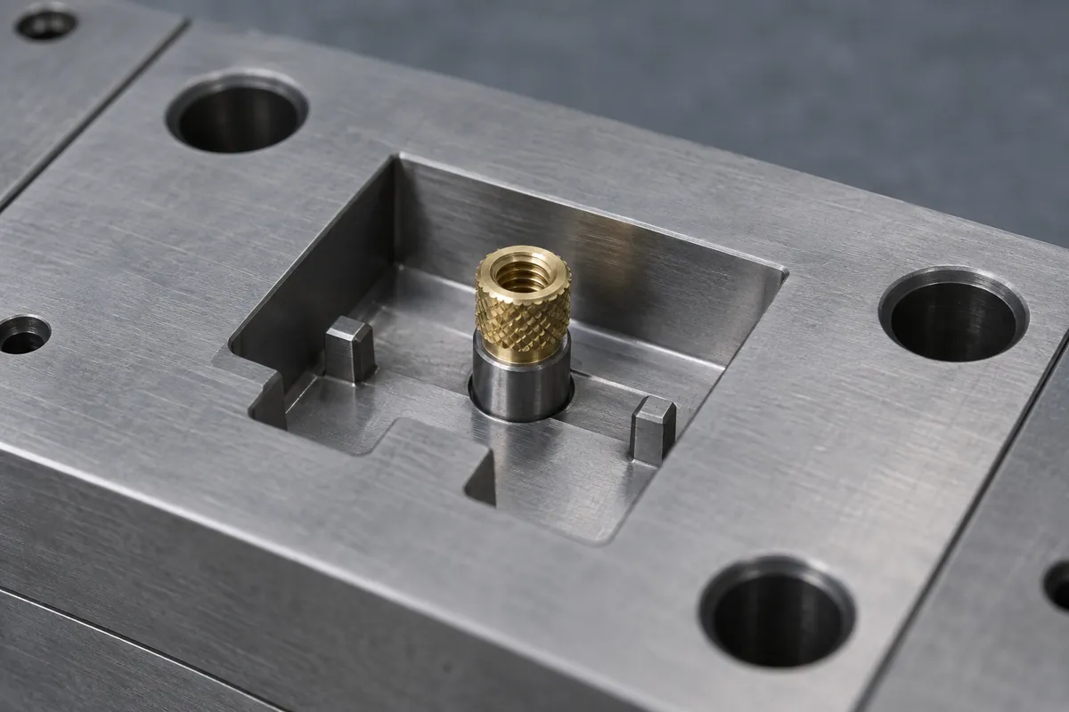
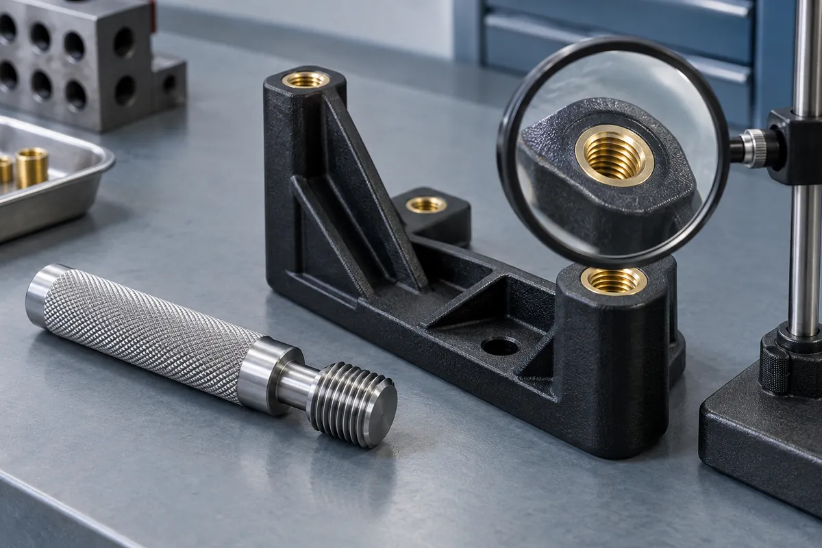
All images in this article are newly AI-generated illustrations of engineering concepts, not photographs of a customer project or evidence of completed testing.
Show the Protected Boundary on the Drawing
Identify the thread designation, fit requirement where applicable, entry side and usable depth. Distinguish a through insert from a blind-end configuration. Show which surfaces may be covered by plastic and which must remain accessible for the intended screw or gauge. If the drawing only labels the nominal screw size, ask the designer to resolve the missing acceptance information.
SPIROL's molded-in insert range includes different configurations for molded applications. The important purchasing lesson is to identify the exact hardware rather than treating all inserts of one thread size as equivalent. Use the selected manufacturer's drawing in the tool review; a catalog category does not define the dimensions of an unspecified part.
Also check the assembly stack. The screw, mating plate and any washer determine the engagement available when the joint is seated. Do not change screw length as an informal response to a blocked or shallow opening. Confirm whether the issue is contamination, thread condition or an assembly-depth conflict before deciding the correction.
Ask How the Tool Protects the Opening
The tooling proposal should explain how the insert is located, supported and presented to the surfaces intended to prevent resin entering the protected region. Have the tool designer identify relevant insert tolerances and access for loading. This is a review question, not a recommendation to use one universal pin or plug arrangement.
A nominal CAD model cannot show all incoming variation. Ask how the proposed contact and location scheme responds to the approved insert tolerance range, and how a missing, misoriented or incorrectly seated insert will be detected. The project needs a practical control method, but this article does not assume a particular sensor or automated loading system is available.
Where a trial reveals flash near the thread entry, record its location before changing the process or hardware. Compare affected samples with the incoming insert lot and the relevant tool features. A photograph can guide the investigation, but it is not enough to establish which tolerance or process condition caused the leak path.
Visual, Gauge and Assembly Checks Have Different Jobs
Visual inspection can reveal obvious debris, flash or entry damage. An appropriate thread gauge addresses the specified thread requirement under its agreed procedure. A functional assembly check addresses the intended screw and mating components. Select the combination from the actual requirement rather than describing all three as the same test.
Where GO/NO-GO gauging is specified, identify the gauge standard or specification, size, class, condition and method in the inspection plan. A production screw is not automatically a calibrated substitute. Conversely, a passing thread check does not prove that the insert pattern aligns with the mating part or that the insert will resist the required load.
| Requirement | RFQ input | Inspection record |
|---|---|---|
| Thread identity and access | Designation, class if required, entry and usable depth: ____ | Insert specification, drawing revision and feature ID. |
| Thread condition | Visual criteria, gauge specification and procedure: ____ | Gauge ID/status, result and any obstruction or damage. |
| Assembly usability | Screw and mating-part revisions, engagement procedure: ____ | Seating/fit result, exceptions and disposition authority. |
Do Not Let Rework Erase the Evidence
If a defect is found, hold and identify the affected material. Do not routinely run a tap through every insert and call the operation inspection. A corrective operation changes the part and may create debris or alter the thread; its method, cleaning and reinspection need approval from the responsible team.
Record the original defect separately from the final disposition. A lot that was accepted after approved rework has a different history from a lot accepted without correction. Keeping that distinction visible helps the next investigation and allows purchasing to understand the real delivered process rather than an unexplained extra operation.
Build a Small but Complete RFQ Package
For a custom injection-molded bracket, send the bracket drawing, exact insert drawing and the screw/mating-part information together. Mark the protected regions and explain who owns any unresolved thread or depth requirement. Add the agreed checks to the quotation rather than waiting until a finished sample reaches assembly.
For customer-owned hardware, connect this requirement to the incoming insert and lot-traceability plan. Use the datum inspection guide for pattern location, and the retention-test guide for mechanical acceptance. Request a review of your insert-molded bracket and thread requirements.