
Illustrative engineering design study
Threaded-Insert Bracket: Location, Boss Geometry & Validation
What needs to be resolved before a two-insert mounting bracket is ready for tooling and sample approval?
The hypothetical brief
A bracket must locate two screws—and survive the intended assembly.
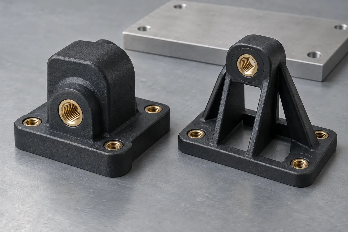
Assume a plastic mounting bracket for non-safety-critical equipment, with two metal threaded inserts and a mating plate. The owner wants the screws to align, the mating surfaces to seat and the connections to satisfy an agreed retention requirement. Dimensions, resin, insert type and load limits remain open.
The study separates three decisions that a drawing review can otherwise bundle together: how the inserts are located, how the surrounding plastic is shaped, and how the finished part will be judged. Increasing material around an insert does not answer all three questions. Neither does adding ribs or selecting a catalog insert with a high published test value.
This is a proposed investigation for a custom injection-molded bracket. It does not select a winning design. SPIROL's application-testing guidance informs the need to evaluate the actual configuration rather than transplant catalog performance into a new part.
Step 1 · Define the interface
Establish the reference surfaces before checking the pattern.
Use the mounting face, a side reference and an end reference to discuss how the hypothetical bracket sits in its assembly. The sketch below labels them A, B and C for discussion only. The designer must establish the formal datum system, tolerances and restraint condition on the controlled drawing.
Record the location and relevant orientation of each threaded feature, then assess the mating assembly separately. A pattern-spacing result cannot alone establish its position relative to the mounting face. The datum inspection guide explains the difference between an insert's visible rim, a measured axis and a functional fit check.
Step 2 · Compare geometry
Two boss concepts, neither approved in advance
Concept A · Broad surrounding mass
Retain a relatively heavy region around the insert. Investigate how the section transitions into the base, how the part is formed and cooled, and what the geometry contributes under the specified loading.
Open question: Does the section create manufacturing or part-shape concerns that would require a geometry change?
Concept B · Relieved, rib-supported boss
Propose a cored or relieved region with ribs connecting the boss to the bracket. Review remaining material, transitions, tooling access and how the loads reach the mounting surfaces.
Open question: Can the relief be formed and inspected while preserving the required interfaces and mechanical performance?
| Review area | Concept A | Concept B |
|---|---|---|
| Plastic distribution | A broad mass surrounds the insert. Review section transitions, cooling and the relationship to adjacent walls. | A relieved region separates some material from the insert boss. Review the remaining ligament, rib junctions and local filling. |
| Insert location and support | Define the surfaces that locate the insert and carry molding loads; surrounding mass does not locate the insert by itself. | Define the same location requirements, then check whether the relief limits access or tool support. |
| Mold construction and release | Review core access, draw direction, parting surfaces, gate/vent proposals and ejection. | Review the geometry needed to form the relief and ribs; do not assume the added details release without tooling consequences. |
| Mechanical behavior | Assess the finished geometry using the agreed support and load directions. No superior retention is assumed. | Assess the finished geometry under the same functional requirements. Ribs are a design proposal, not proof of strength. |
| Inspection and assembly | Keep mounting references, usable thread, position and mating fit explicit. | Preserve those requirements while checking access to inspect the relieved region and any changed surfaces. |
Keep the required assembly interfaces constant when comparing the concepts. Any proposed change to insert specification, resin or test setup should be visible; otherwise the review may appear to compare geometry while changing several variables at once. A chosen design still needs complete tooling and application validation.
Step 3 · Plan the evidence
Define the validation plan before testing.
The following is a proposed plan, not an executed test report. Agree specimen quantities, conditioning, methods, equipment suitability and acceptance ownership before testing. Use separate specimens for destructive checks unless an intentional sequence has been justified.
| Check | Define first | Record | Acceptance basis |
|---|---|---|---|
| Insert identity and thread usability | Controlled hardware, protected regions, approved thread/gauge procedure and usable engagement. | Insert lot, drawing revision, gauge identity and individual findings. | Approved specification; no forced screw entry or unapproved corrective tapping. |
| Location and part condition | Datum scheme, measured insert feature, fixture/support, conditioning and assembly state. | Feature-level measurements, setup revision and fit observations. | Drawing requirements and separately defined functional fit. |
| Axial retention | Specimen group, load axis, engagement, fixture support, settings and failure definition. | Individual readings, displacement/observations and identified failure location. | Project requirement and limit approved before acceptance testing. |
| Rotational retention / assembly | Separate torque-out method from ordinary screw tightening; define the reaction path. | Rotation, thread/host damage, fixture exceptions and the exact tested configuration. | Applicable method-specific criterion; no torque-out-to-tightening conversion is assumed. |
| Repeat assembly if required | Service sequence, fastener reuse/replacement, environment, intervals and sample allocation. | Completed sequence and findings at agreed inspection points. | Approved service requirement; no generic lifetime or cycle count. |
Thread usability, dimensional fit and retention should remain separate results. A bracket that passes one does not automatically pass the others. Review the torque/pull-out worksheet and service-cycle plan for the relevant scope. Record fixture failures or interrupted tests rather than removing them without explanation.
Step 4 · Decide what can be released
Keep open decisions visible through sample approval.
Freeze the inputs
Confirm resin, insert, bracket and mating-part revisions, loads, environment and drawing requirements.
Review the tool concept
Resolve insert support, thread protection, plastic geometry, tool release and inspection access.
Review actual evidence
Assess identified trial parts and test records against approved criteria; retain failures and deviations.
Record the decision
Release only the supported scope, or assign changes and repeat checks before production authorization.
If the customer supplies the hardware, the insert traceability plan should connect each test and finished batch to incoming material. Future changes to source, surface condition or geometry need a documented assessment of whether the existing evidence remains applicable.
Apply the review to your bracket.
Send the real CAD, insert drawing, mating hardware and acceptance requirements. Identify what is fixed and what remains open. FECISION can then discuss a project-specific insert-molding scope for your custom mounting bracket.