
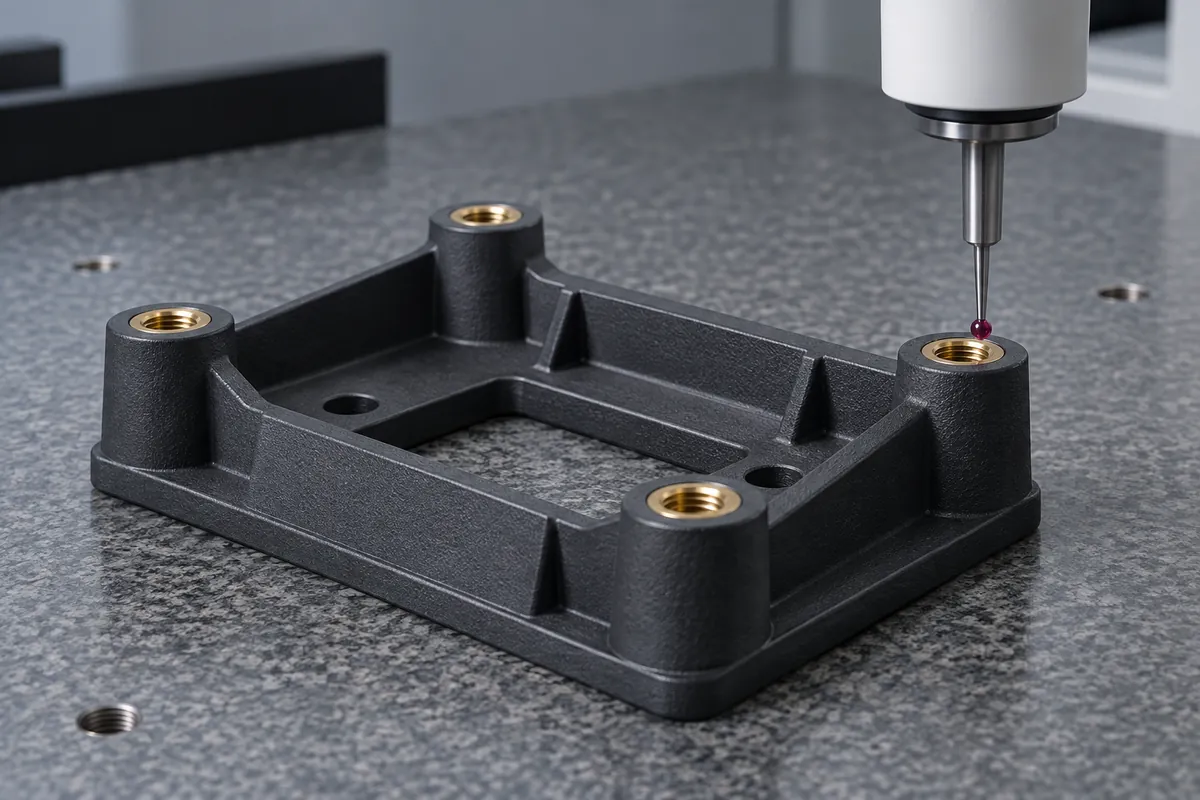
Both holes are the right distance apart, yet the bracket does not fit the assembly. This is possible when an inspection reports only center-to-center spacing and ignores where the pattern sits relative to the mounting surfaces. It is also possible when the measuring setup pulls a flexible bracket into a shape that the real assembly does not reproduce.
Multi-insert inspection needs a defined reference frame and a defined part condition. Before asking for a CMM report, agree which assembly features establish the bracket's location and what feature of each insert will actually be measured. The aim is a repeatable approval decision, not simply a longer list of decimal places.
All images in this article are newly AI-generated illustrations of engineering concepts, not photographs of a customer project or evidence of completed testing.
Start with the Mating Assembly
For a conceptual bracket, imagine a mounting face that seats against a plate, a side feature that establishes direction and an end feature that establishes the remaining location. Call these review references A, B and C. They illustrate the questions to ask; they are not a complete GD&T specification or a substitute for the released drawing's datum system.
Identify which features the real assembly actually contacts. A convenient outer edge may have little relationship to the functional interface. If the drawing is missing a reference scheme, resolve that with the designer instead of allowing each inspector to choose a different edge and calling the resulting reports equivalent.
ZEISS discusses consistent datum selection, alignment and fixturing in its CMM inspection guidance. The practical purchasing implication is to request the measurement method as well as the instrument name. “Measured on a CMM” alone does not tell the reviewer how the coordinate system was established.
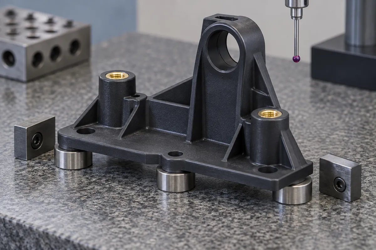
Decide What Represents the Threaded Axis
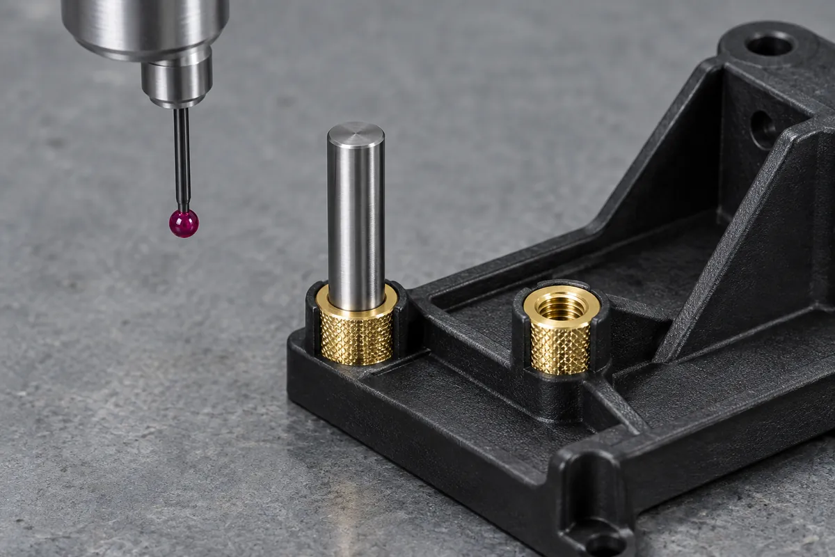
An insert has several inspectable features, and they are not automatically interchangeable. Its visible outer rim, pilot, internal thread and a threaded gauge mounted in it may represent different measurement targets. Ask the inspection owner how the functional threaded location will be established and what uncertainty or fit is introduced by the chosen method.
A temporary threaded mandrel, for example, needs a defined seating procedure and a reason it represents the feature being controlled. Do not assume that a quick measurement on a screw head establishes the insert's true axis. The drawing requirement, gauge design and measurement method must be consistent, including whether orientation as well as location matters.
Record each insert separately. Calling a two-insert pattern “within tolerance” can conceal that one position is near its limit while the other is comfortably centered. Keep feature identifiers that connect the drawing, report, fixture and any later assembly complaint. This creates a useful path back from a failed fit to a specific characteristic.
Free-State and Restrained Checks Answer Different Questions
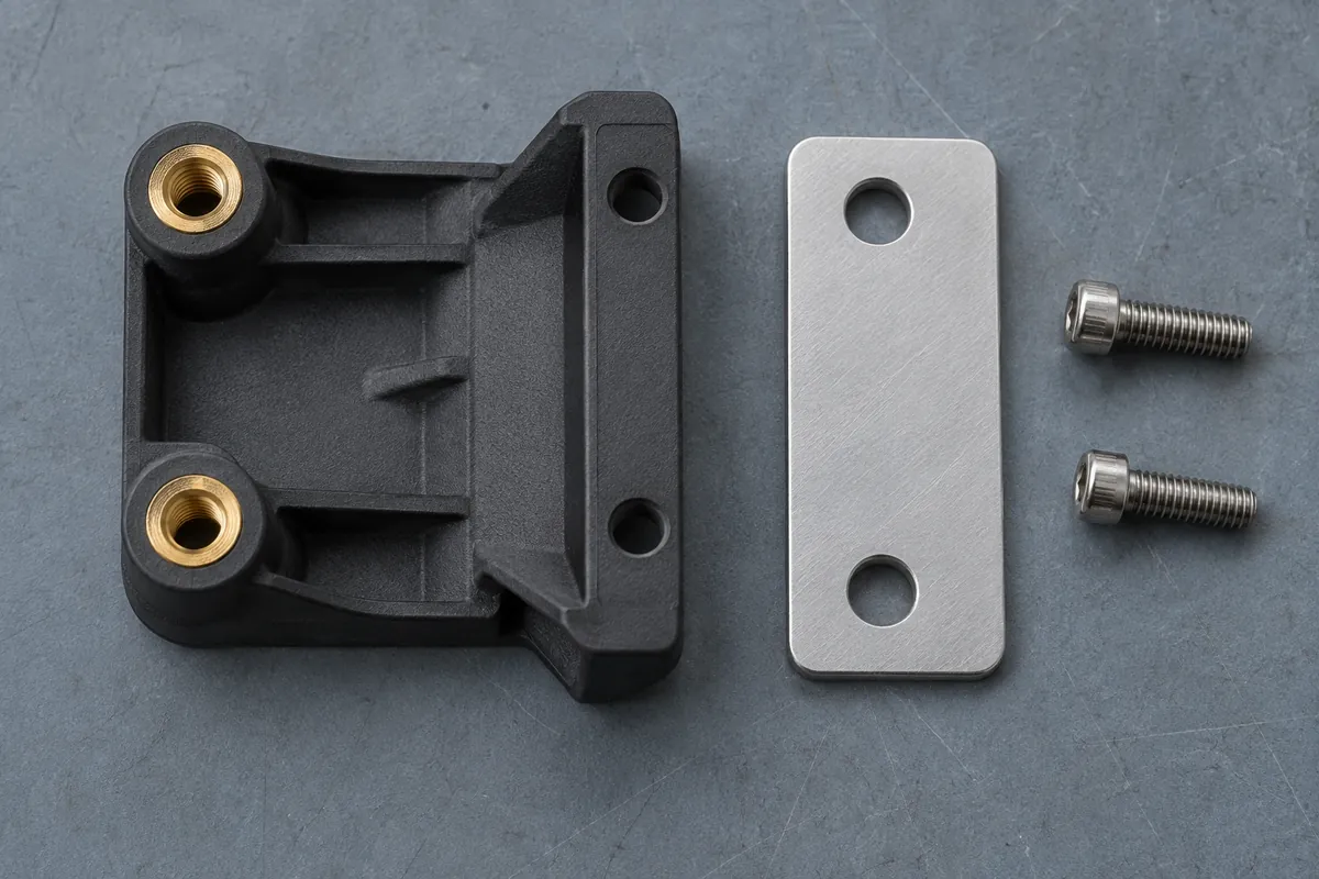
A part measured with no assembly restraint can differ from the same part held against a mounting plate. Neither condition is automatically the correct one for every characteristic. Define the required state from the drawing and functional requirement, then document support points, clamp positions and any specified restraint procedure.
If a bracket fits only when it is forced down hard, an inspection should not erase that observation by using stronger clamps. Equally, a design intentionally defined in an assembled condition should not be rejected against an unrelated free-state assumption. The appropriate response is to resolve the condition, not to adjust the setup until the numbers become comfortable.
Write the Report Requirements Before Measuring
The worksheet below is an inspection-planning aid. It deliberately avoids a universal positional tolerance because the mating hardware, resin, geometry and application determine what is needed. Mark open drawing questions before accepting a quotation that promises an unexplained accuracy figure.
| Feature group | Method to agree | Report requirement |
|---|---|---|
| Datum references and part state | Drawing scheme, supports, restraints and conditioning: ____ | Alignment and fixture revision, not just equipment name. |
| Each insert location and orientation | Measured feature, gauge or probing method: ____ | Individual feature IDs, measured values and applicable limits. |
| Mating assembly fit | Plate/gauge revision, screw procedure and fit criterion: ____ | Observed fit and exceptions, separate from dimensional acceptance. |
Include a remove-and-reseat check when establishing the inspection method. If the reported location changes with setup, investigate the measurement arrangement before attributing all variation to molding. This is a proposed method-development check, not a claim that any particular measurement system has already been validated.
Do Not Diagnose Shrinkage from One Measurement
A position difference can prompt several investigations: insert location in the tool, part shape, conditioning, drawing interpretation or inspection repeatability. Compare identified samples using a controlled method before assigning a cause. The measurement is an observation; the proposed manufacturing explanation is a separate conclusion that needs evidence.
The bracket design study includes an original datum sketch and a proposed review sequence. Use it to organize questions for your own multi-insert mounting bracket. For a broader release package, connect the measurements to first-article approval. Send the bracket and mating-part drawings for an inspection-scope review.