
Illustrative engineering study · September 28, 2026
Shaft, Plastic Bushing and Housing: A Fit Design Study
A loose bore measurement and an installed running-clearance check answer different questions.
The design question
Which condition does the bore requirement represent?
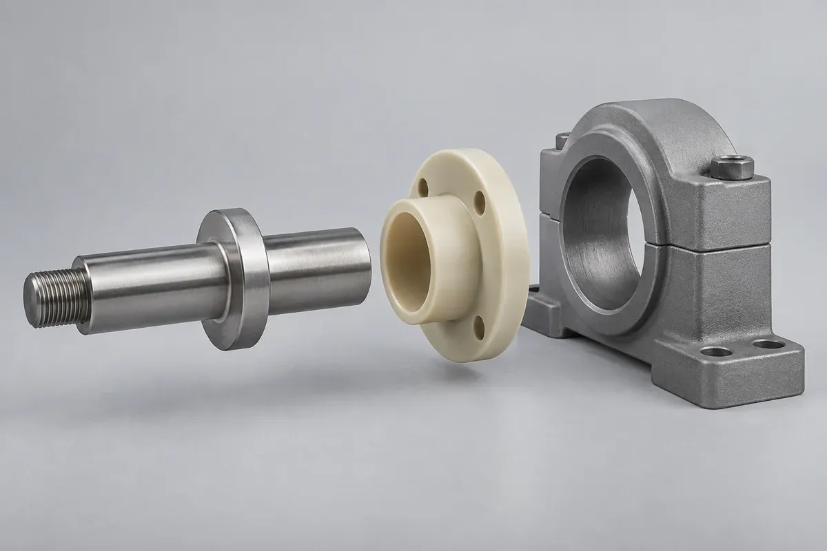
Consider a polymer bushing installed in a rigid housing to guide a shaft. The housing retains the bushing, while the shaft requires an agreed clearance for its intended movement. The exact material, interference, load and operating environment remain open in this hypothetical review.
The question is whether the drawing and inspection plan adequately distinguish the loose bushing from its installed state. A part can meet a free-state bore requirement without proving the final shaft relationship. Installation, restraint and specimen condition need to be included in the definition.
Hold shaft and housing revisions constant while comparing the proposed bushing concepts. If the housing bore or shaft finish changes during development, identify the change separately. Otherwise the team cannot distinguish a material or geometry effect from a counterpart change.
Concept comparison
Compare retention and guidance without mixing their roles.
Concept A uses a straight sleeve with a specified housing-retention arrangement. Concept B uses a flanged sleeve to add an explicit axial locating interface. The flange does not automatically establish the desired radial fit, and the straight sleeve still needs a defined retention strategy.
For each concept, trace radial and axial loads to their supporting features. Identify whether the shaft contacts a flange face and whether movement is continuous, oscillating or only part of installation. A bearing duty should not be inferred from the word bushing alone.
The material candidate must also be identified by exact grade. A proprietary bearing compound's published data cannot be assigned to every molded POM or nylon sleeve. Use the material review guide to organize the needed evidence.
Interface definition
Treat installation and operating condition as inputs.
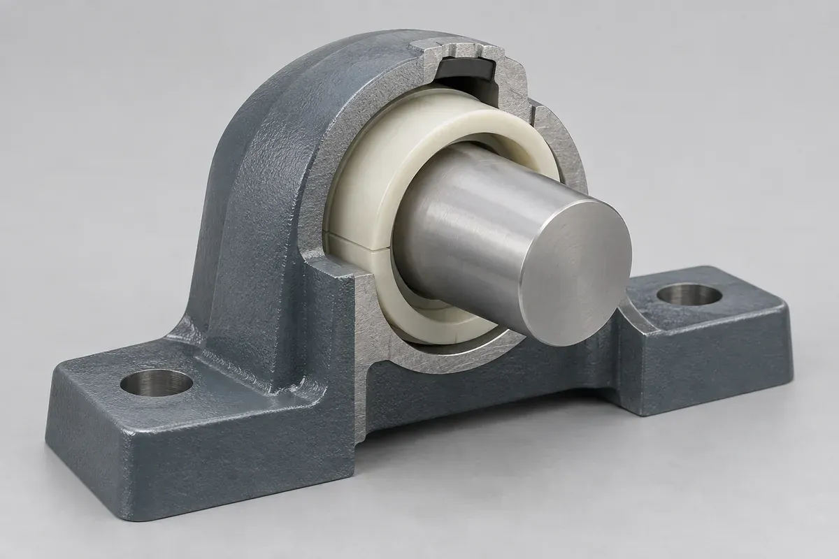
Document the housing size and form, bushing geometry, shaft definition and assembly method. Include the material condition and the state in which dimensions apply. A nominal diameter alone cannot describe the complete installed relationship.
Review how the part is inserted and seated. An installation fixture that distorts a flange or fails to support the intended surface can introduce a different problem from the fit design. Preserve those observations instead of assuming all resistance is caused by an undersized bore.
| State | Question | Evidence to agree |
|---|---|---|
| Loose component | Does the identified bushing meet its free-state requirements? | Drawing measurements with specified support and condition. |
| Installed component | How does the retained bore relate to its specification? | Agreed installed-state gauge or measurement method. |
| Shaft assembly | Does the actual pair meet the required fit and movement? | Controlled counterpart check and separately scoped operating evaluation. |
Use the press-fit guide for the distinction between these states. The table is a proposed sequence, not proof that a particular assembly meets its limits.
Proposed verification
Preserve specimen identity through the assembly sequence.
Measure identified loose samples before installation. Record the selected grade, drawing revision, relevant production identity and condition. Install them in controlled housings using the agreed method, then evaluate the installed bore before adding the shaft where the plan requires it.
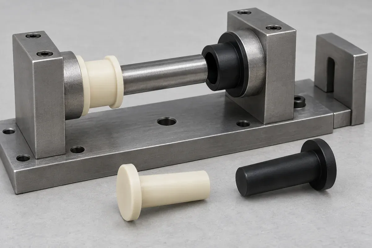
Use the specified shaft for the assembly check and record surface condition and any lubrication. A convenient substitute shaft can answer an early envelope question but should not be treated as the approved counterface. Likewise, lubricant added to ease a trial changes the configuration.
If environmental conditioning is relevant, define how it relates to the assembly states and required observations. Do not infer an installed clearance change directly from a generic free-material percentage. The actual constrained configuration needs the agreed evaluation.
Investigation plan
Investigate binding without silently changing the trial.
If the shaft binds after installation, compare the recorded loose and installed states before enlarging the bore. Check whether the specimen is fully seated, whether the housing and shaft match their controlled definitions, and whether the agreed condition was maintained. These checks can separate an interface problem from an assembly deviation.
If movement varies with angular position, inspect the relevant geometry and alignment using a suitable method. Do not automatically attribute the symptom to the resin. A shaft or housing condition can create an observation that looks like a bushing issue when only the assembled motion is examined.
When a trial requires reaming, lubrication or a modified housing to continue, record that intervention as a new configuration. Preserve the original observations. The modified assembly may support further learning, but it cannot be reported as an untouched sample meeting the original specification.
The next revision should state what is changing and why. That record prevents a production order from inheriting an undocumented prototype workaround and keeps the quotation aligned with the component that was actually approved.
Release boundary
Separate fit approval from operating-life claims.
A real trial might lead to a revised bore, wall, flange, material or housing interface. Each option must be evaluated against the complete requirements. This study does not identify a universally correct interference or claim that one concept has lower wear.
After the agreed component and fit checks, any required wear, load or life evaluation remains a separate responsibility. State the operating conditions and acceptance method before making performance claims. Smooth motion during a short hand check does not establish long-term suitability.
The useful result is a controlled relationship between the drawing, installation process and inspection state. It lets a buyer request a quotation for a defined molded component while keeping unverified bearing performance outside the promise.
Apply the review to your part
Turn your drawing into a defined review.
Provide the bushing, housing and shaft definitions with the intended motion, exposure and inspection state. Resolve the installed fit before assigning operating performance.
Explore our custom injection-molded plastic bushings or the broader injection molding service.