
Illustrative engineering study · September 24, 2026
Protective-Cap Retention and Removal: A Design Study
Protection, retention and clean removal are separate requirements. Define where a cap or plug may touch before choosing its appearance.
The design question
What needs protection—and what must remain untouched?
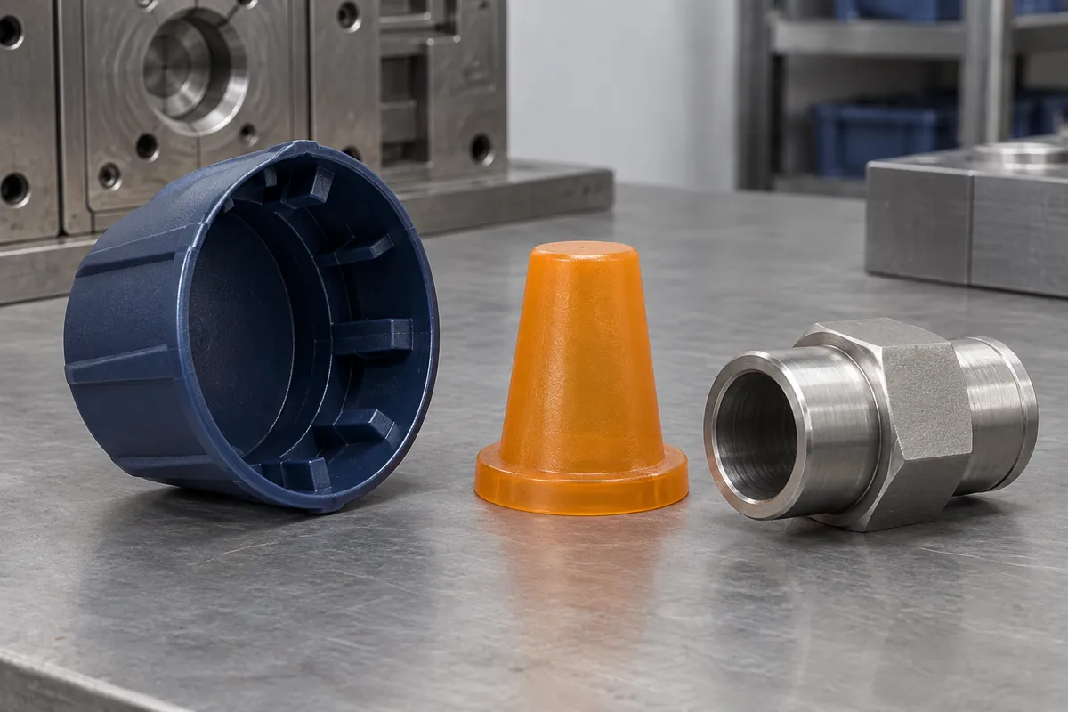
Consider an industrial interface that needs temporary protection during handling and shipment. Its outer surface, opening and nearby functional features are defined on a counterpart drawing. The purchaser has not yet approved the protector's contact region, retention requirement or removal method. No sealing function is assumed.
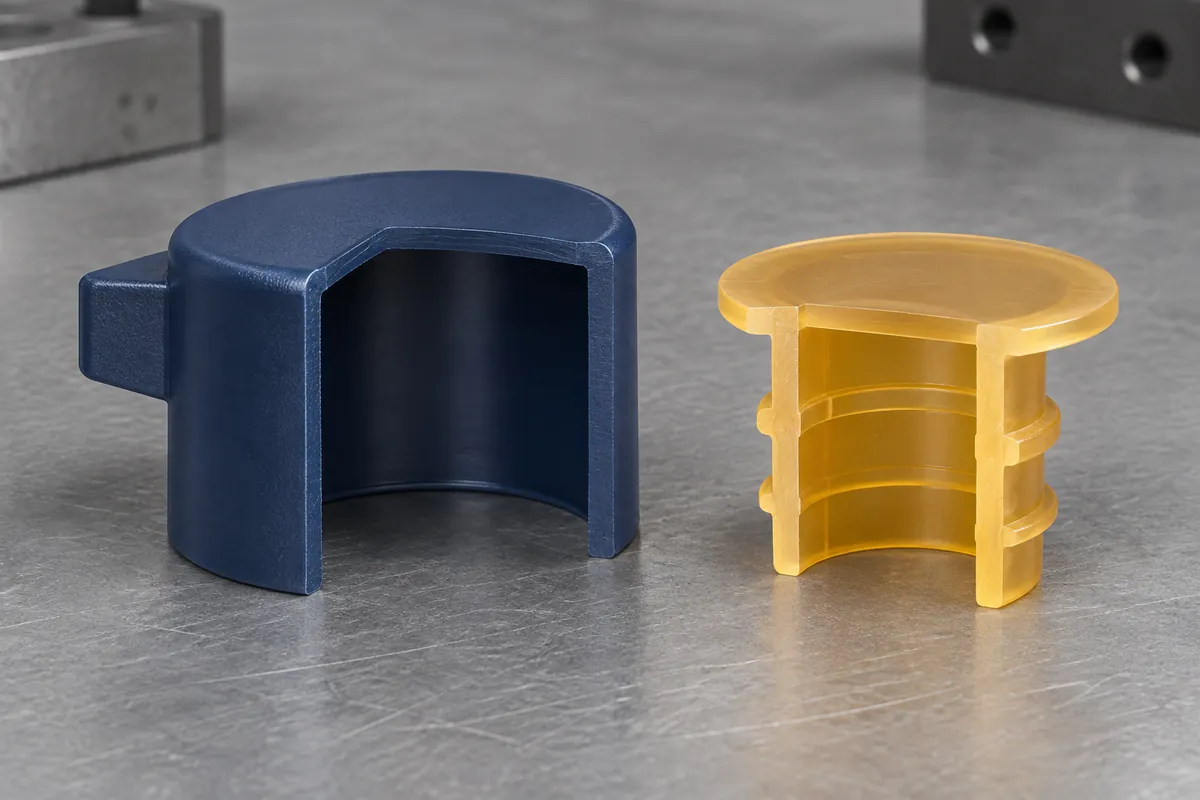
Concept A is an external cap fitting over the outside surface. Concept B is an internal plug engaging the opening. Each can cover an exposed interface, but each touches a different area. Choosing between them requires more than comparing the visible shape or material cost.
Begin by marking protected surfaces, permitted contact and keep-out regions. A plug may be unsuitable if the bore must remain untouched; a cap may conflict with an external coating or neighboring feature. These are application decisions to resolve with the owner, not universal advantages of one concept.
Concept comparison
Move the contact zone, and the review changes.
The section sketches show only the interface relationship. Gold lines identify candidate contact regions; they are not specified interference values, sealing lands or verified retention features. The real geometry needs draft, thickness, release and tolerance review before tooling.
For the cap, review the outside diameter or profile, surface finish, edge geometry and insertion depth. For the plug, review the opening, internal obstructions and permitted penetration. In both cases, identify a stop condition so the installation method does not depend on an undefined amount of force.
A design may use flexibility, local ribs or another retention approach. That choice must remain linked to the exact material and counterpart. Appearance alone does not establish removal effort, contamination risk or suitability after storage. The fit and retention guide separates those questions.
Proposed evaluation
Cover the counterpart variation without inventing limits.
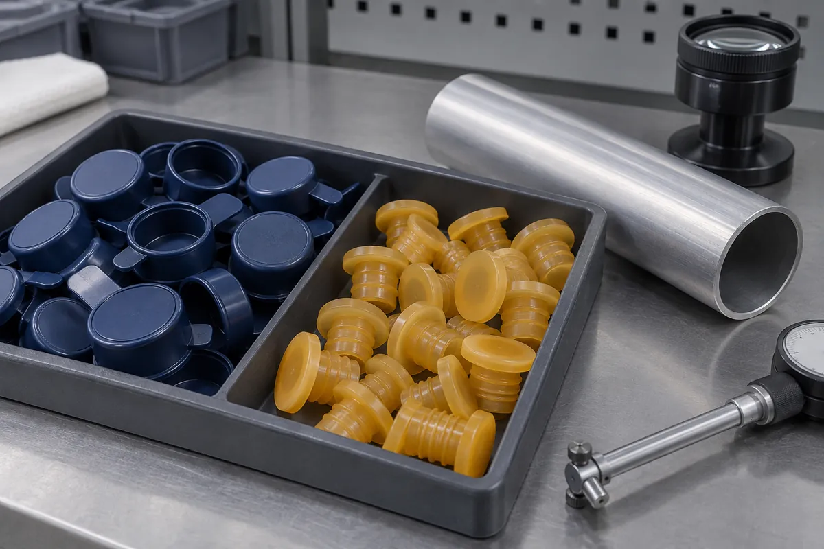
Build the comparison around approved counterpart limits and relevant surface conditions. “Lower,” “nominal” and “upper” refer to the actual drawing requirements, not numerical values invented for this example. The sample matrix should also identify the protector configuration and its manufacturing history.
Define installation alignment, speed or action, travel and the observation used to confirm seating. Distinguish the peak during insertion from any final seated response. An operator's description of “a tight fit” cannot replace an agreed method where a measured acceptance value is required.
| Stage | Inputs to agree | Record to retain |
|---|---|---|
| Counterpart selection | Approved limit conditions, surface state and identifying revision. | Identity and condition of each counterpart used. |
| Installation | Alignment, support, action, travel and seating definition. | Individual observations and any specified force/travel data. |
| Retention exposure | Actual handling or storage scenario, duration and environment. | Configuration, exposure history and required retained function. |
| Removal | Access, tab action, withdrawal path and permitted reuse. | Removal observations, damage, fragments and surface condition. |
Instron's testing-accessory overview shows that a measurement setup depends on the action being evaluated. For a real cap project, suitable fixtures and a validated method still need agreement. No equipment-based result has been generated for this study.
The material and service boundary
A shipping protector is not automatically a masking product.
Candidate LDPE, PP or TPE grades should be screened against the actual stiffness, flexibility, exposure, cleanliness and processing requirements. A family name alone does not establish performance. Colorant, exact grade and geometry belong to the configuration and should remain visible when samples are compared.
If the part is intended for a coating process rather than shipment, reopen the requirements. Define the chemistry, exposure profile, protected region, removal timing and reuse policy. Caplugs' masking reference treats masking products as application-specific selections. It does not justify assigning a masking-temperature rating to an untested custom shipping cap.
After the agreed exposure, inspect the protector and counterpart. Record residue, loose fragments, witness marks and any blocked feature separately from retained fit. A part can remain attached while failing a cleanliness or surface-protection requirement. Preserve those observations even if a force result appears acceptable.
Decision and release
Choose against an agreed function, not an attractive render.
The output of this study is a defined comparison and a proposed evaluation record. The design owner might select the external cap, develop the internal plug, change the removal feature or reject both concepts. There is no demonstrated improvement in retention, installation time or damage prevention.
Before tooling, close the protected-surface map, counterpart revision, exact material, installation and removal method, exposure conditions and acceptance ownership. Keep development observations separate from production approval. If the material, contact ribs or counterpart finish later changes, assess whether the existing evidence still applies.
A custom molding quotation can then identify the delivered component and its agreed checks without implying a pressure seal, certified protective rating or off-the-shelf fit. That clear supply boundary is more useful than a generic promise that one cap will suit every port of a similar nominal size.
Apply the review to your part
Turn your drawing into a defined review.
Send the counterpart drawing and mark what must be protected, what may be contacted and how the protector will be installed and removed.
Explore our custom molded protective caps and plugs or the broader injection molding service.