
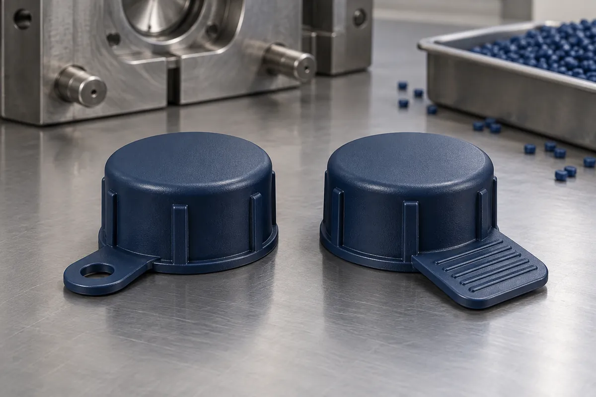
A removal tab can look generous in a CAD view and become almost unreachable once the protected fitting is inside its packaging or equipment enclosure. Enlarging the tab may help access but introduce another problem: it can catch on nearby parts during transport or load the cap in an unintended direction.
Design the tab around the intended removal action and the space available for it. Review access, the load path into the cap, material response and molding together. A stronger-looking tab is not automatically a better protector, and a tab that tears before removal is not necessarily proof that its root is the only problem.
Product design illustrations. Final geometry, materials and acceptance criteria are project-specific.
Draw the removal sequence, not only the tab
Show the installed cap, the surrounding component and the available approach. Identify whether removal uses a grip, a hook or an agreed tool. State the intended direction and whether the cap is lifted, peeled or pulled axially. This makes the design discussion more concrete than “make it easy to remove.”
Consider the location of the part at the actual removal stage. Packaging, neighboring fittings or a recessed port can restrict access. Do not approve the action using an isolated tube if the real assembly blocks the grip surface. If a tool is required, include its access envelope and any restriction on contacting the protected component.
Separate tab failure from excessive retention
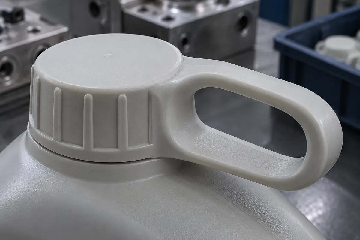
If a tab fails, record the complete event: seating condition, counterpart, exposure, direction of pull and the point where damage begins. The cause might involve local geometry, material, molding or a retention requirement that demands an unsuitable removal action. Increasing thickness without reviewing the system can simply move the failure elsewhere.
Use the fit and retention plan to define the cap's engagement. Then define what the tab must do to release that engagement. Retention against accidental detachment and deliberate removal can be evaluated separately, with their own method and acceptance criteria.
Review the root and grip area together
The tab needs a usable grip area and a transition into the body that can support the intended action. Review radii, thickness transitions and any notch-like features with the selected grade. Avoid prescribing a universal root radius or thickness ratio without the geometry and material data.
Texture may help a grip surface, but it also affects tooling and the interpretation of surface requirements. Keep texture off surfaces where it would interfere with the protected component or an inspection method. If lettering or an orientation mark is required, specify it rather than adding arbitrary molded text to the concept.

| Area | Question | Evidence to request |
|---|---|---|
| Access | Can the intended grip or tool reach the tab in the actual assembly? | Controlled assembly model or identified fit trial. |
| Load path | How does the removal action load the tab root and cap wall? | Defined method and observations on representative samples. |
| Handling | Can the tab snag, fold or interfere before removal? | Relevant packing and handling evaluation. |
| Molding | Are the gate, parting line and release route compatible with the tab? | DFM review and actual sample inspection. |
Check how the feature will be molded
Review gate location and filling around the tab root, along with the mold opening and ejection direction. A convenient gate location for filling can leave a witness in a grip or contact area. Protolabs explains this gate-vestige tradeoff in its gating reference; the custom protector still needs its own proposal.
Do not assume that a flexible part can always be stripped over an undercut. The release route should be reviewed for the chosen geometry and material condition during ejection. If a side action or another tool feature is proposed, keep that commercial and maintenance scope visible in the quotation.
Test a repeatable action
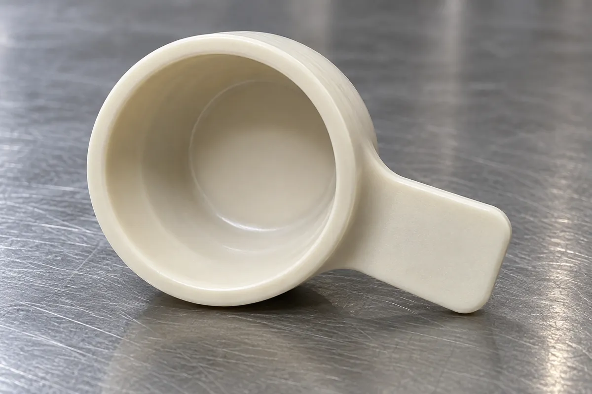
Identify the fixture, grip point, pull direction, movement and part condition. State whether the test is performed immediately after installation or after a defined exposure. If repeated use is required, preserve the cycle history and the rule for replacing the counterpart.
Record force information where required, but also document incomplete removal, tearing, fragments and damage to the protected surface. A tab that reaches an attractive peak-force value but leaves the cap stuck has not satisfied the removal function. Keep all observations linked to the specimen rather than selecting only a favorable number.
Before production, approve the complete tab-and-retention configuration and the changes that require review. The inspection guide connects these functional checks with appearance, handling and packaging evidence. The result should be a clear removal requirement, not a claim that one tab shape is universally ergonomic or unbreakable.
Turn the review into a defined molding scope
Explore our custom injection-molded protective caps and plugs and the related illustrative engineering study. Send the drawing revision, counterpart details, intended use and the decisions still open. Development samples and production approval should have separate, agreed deliverables.