
PCB Handling Tray: Stacking and Resistance Review
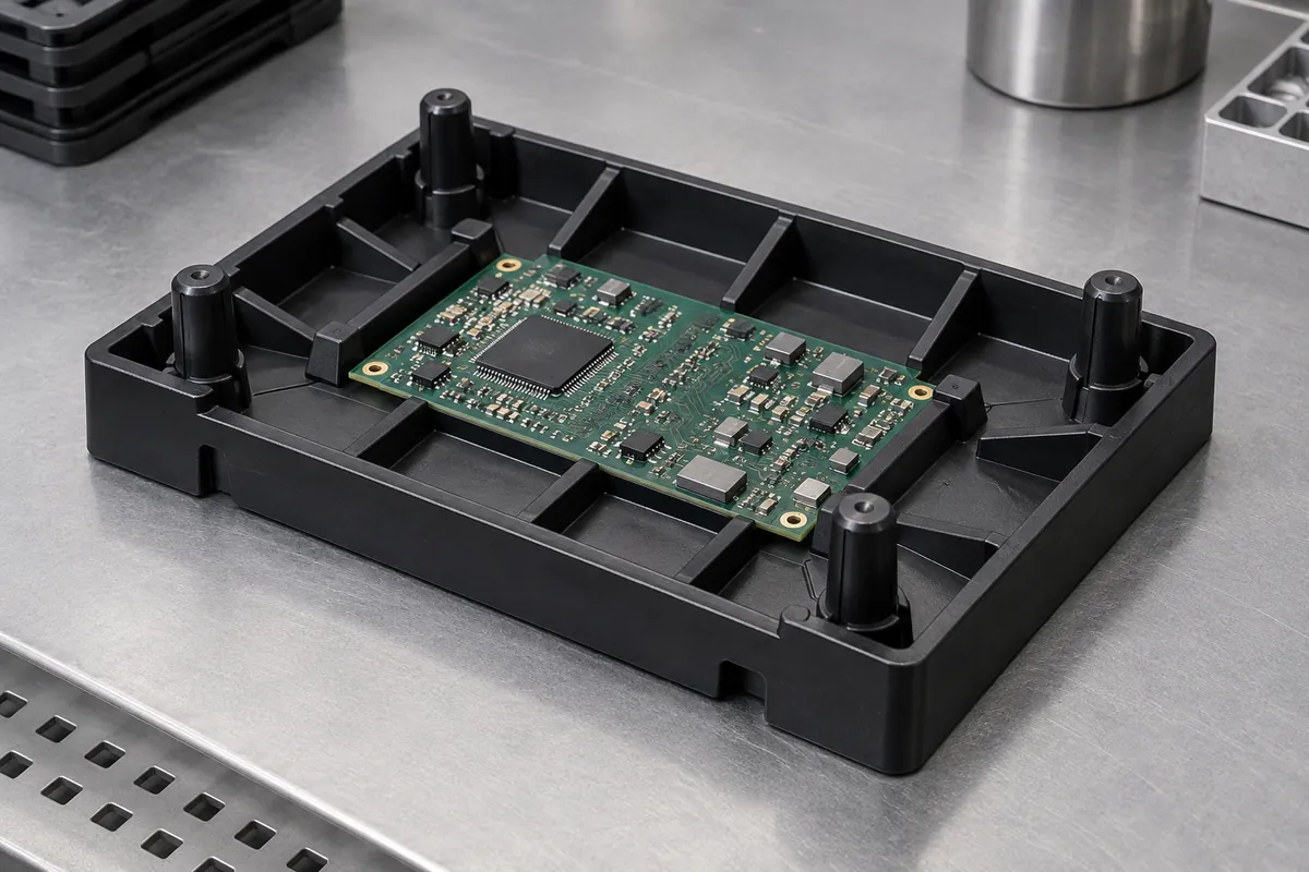
A reusable molded tray was developed to locate electronic components during handling and stacking. The project had to address base deformation, locating-post durability and electrical consistency while preserving the intended component clearances.
The production record reports 15,000 trays delivered through October 5, 2026. Stack and resistance results below describe specific sampled checks; they are not a blanket load rating or a complete ESD certification.
2 cavities
Molded tray tool
15,000 pieces
Reported cumulative delivery
10⁷–10⁸ Ω
Sampled surface resistance
Project background
Component, scope and current phase
| Application | Reusable component-handling tray; customer PCB and equipment details withheld |
|---|---|
| Material | PP-based compound with 15% conductive masterbatch addition; this is not a claim of 15% active carbon-black content |
| Nominal geometry | 350 × 260 × 30 mm tray with four locating posts |
| Manufacturing | Two-cavity injection molding |
| Current phase | Production supply with longer-term tracking still open |
Engineering challenge
What the development work needed to resolve
Initial records described base bowing above 2 mm, stack movement, locating-post damage and variable resistance. The tray needed evaluation as a loaded carrier on defined supports, not only as an empty molded rectangle.
The electrical requirement also needed a controlled compound and test scope. Black appearance or a masterbatch addition rate alone could not establish the finished tray’s protective performance in every handling environment.
Manufacturing review
Changes and the verification approach
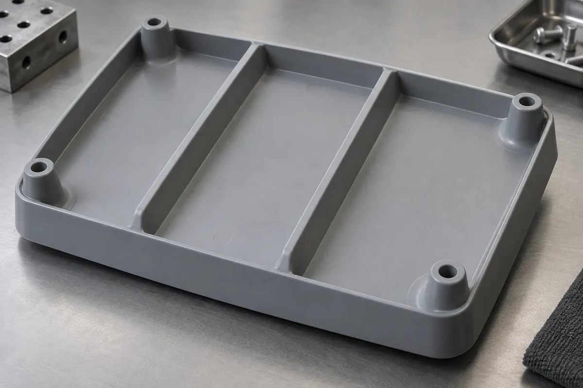
The recorded changes included three reinforcing ribs, larger post-root transitions, an increase in conductive-masterbatch addition from 10% to 15% and a longer cooling interval. These changes were reviewed together with the stacking and component-location functions.
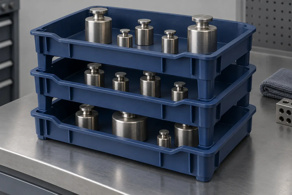
Production checks separated dimensions, loaded stacking and surface resistance. The stack evaluation used three layers and a uniformly distributed 5 kg load. Because the supplied summary does not define every support and hold-time detail, the result remains a bounded project observation rather than a general service rating.
The resistance record identifies a 100 V measurement at three locations on each sampled tray. Conditioning and electrode details were not supplied with the summary, so no complete standard-compliance or ESD certification claim is made. ANSI/ESD S8.1 is not used as a resistance-test method.
T0 · July 15
100 development pieces
T1 · August 1
500 pieces
Production · August 20 onward
15,000 cumulative pieces reported by October 5
Recorded observations
Results with their sample and test boundaries
Each result below applies to the stated specimens and configuration. Development, pilot and production checks are not combined into a single pass rate.
These are owner-supplied project summaries, not independently certified test reports.
| Check | Samples and conditions | Recorded observation | Interpretation boundary |
|---|---|---|---|
| Tray length and location | August 25 production lot; 20 sampled trays | Length 349.8–350.3 mm; locating-post deviation 0.1–0.2 mm | The reported length covers the 350 mm direction only |
| Stack deflection | Five sampled trays; three-layer arrangement with 5 kg uniformly distributed load | 0.8–1.5 mm reported deflection | Specific project setup; no long-duration universal load rating |
| Surface resistance | September 10 production sample; 20 trays, three locations each, 100 V | 10⁷–10⁸ Ω | Project measurement summary; conditioning and electrode details not independently reviewed |
| Wall and ribs | 20 sampled trays | Wall 2.4–2.6 mm; rib height 4.9–5.1 mm | Sampled molding dimensions |
Release status
What is established and what remains open
Production supply had begun, while the planned longer-term tracking remained ongoing. No unsupported production-duration statement or service-life extrapolation is added.
The resistance result does not establish shielding, every ESD protective function or compatibility with every clean-area process. The complete carrier and handling system require their own defined approval.
Published anonymously with the project owner's permission. Original test reports and project photographs were not supplied for this publication review. Images are product design illustrations; no customer or supplier identity is displayed.
Related guides
Plan the next component review
- Injection-Molded vs Thermoformed Trays for Reusable HandlingCompare injection-molded and thermoformed component trays for repeated handling, locating features, stacking, cleaning and total supply scope.
- PP vs HDPE for Injection-Molded Component TraysCompare PP and HDPE for molded component trays using stiffness, impact, cleaning exposure, additives and loaded-part validation rather than resin labels alone.
- Tray Pocket Design: Protect Parts Without Trapping ThemDesign component-tray pockets around support zones, extraction clearance, tolerances, draft and inspection. Protect delicate surfaces without trapping the part.
- Stackable Tray Design: Nesting, De-Nesting and Load PathsDesign stackable and nesting plastic trays with defined load paths, anti-jam features and separation access. Validate loaded stacks and automated de-nesting separately.
- What Makes a Plastic Tray ESD-Safe? Material and EvidenceEvaluate ESD tray claims with the finished compound, resistance method, conditioning and handling function. Distinguish dissipative behavior from shielding and symbols.
- Designing Molded Trays for Robotic Pick-and-PlaceDesign injection-molded trays for robotic handling with controlled datums, gripper access, part orientation, vision conditions and tolerance-aware validation.
Review your component and its mating assembly
Send the drawings, operating conditions, quantities and acceptance methods to define tooling, molding and inspection.