
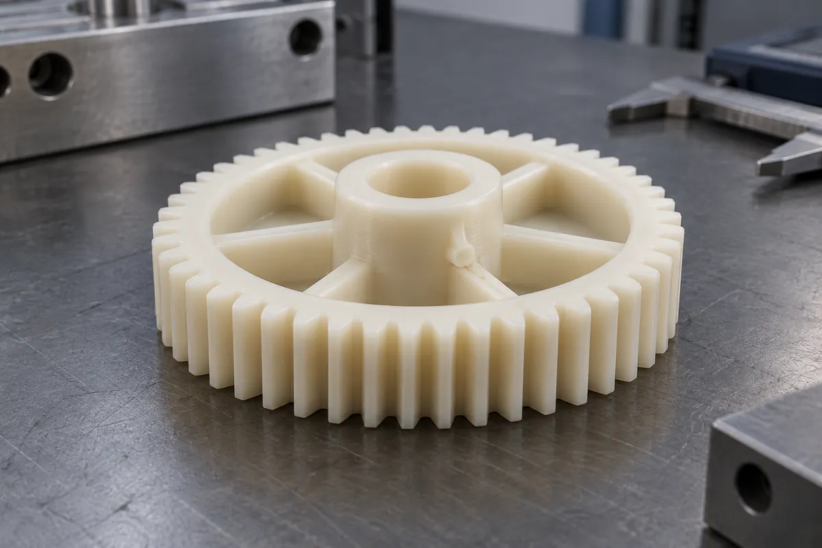
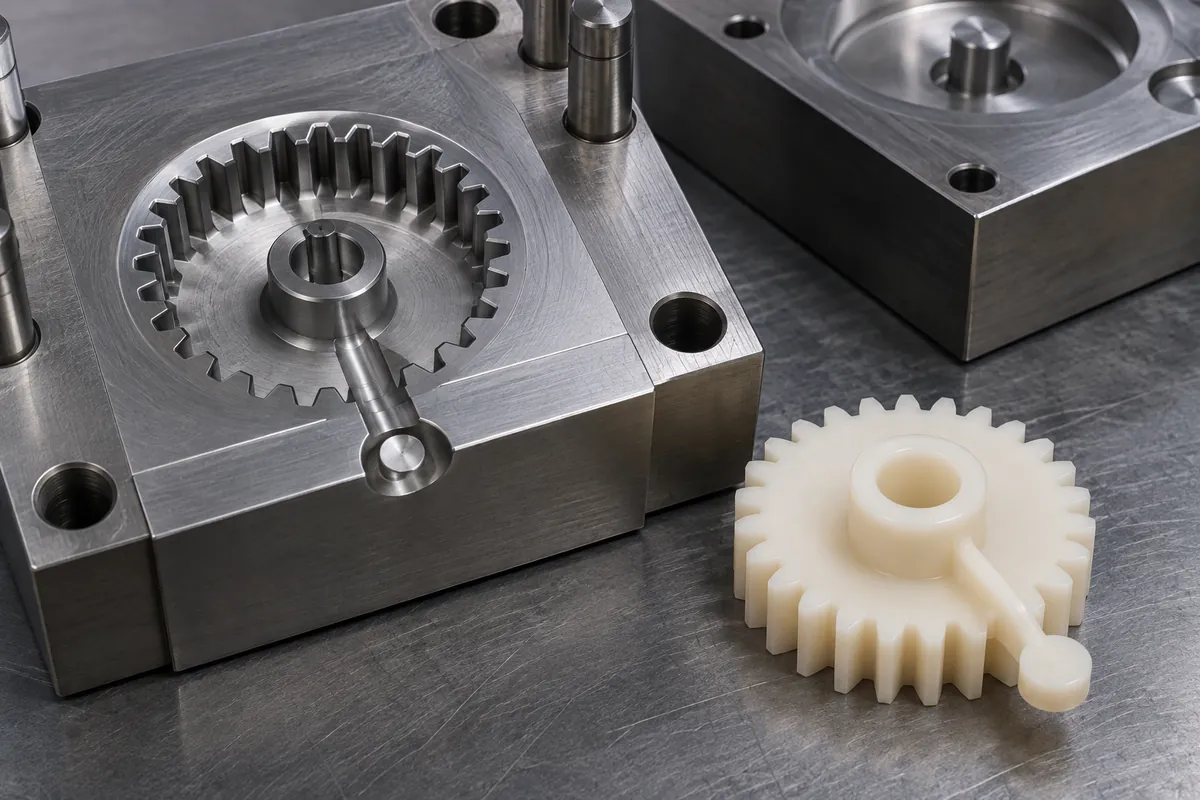
The gear teeth usually receive the most attention on a drawing, yet the gate and central hub can decide how practical the part is to mold and inspect. A thick hub joined abruptly to a thin web, or a gate vestige placed on a critical locating surface, can complicate an otherwise attractive tooth design.
Review the feed location, hub, web, rim and ejection together before committing to a mold. The objective is not to prescribe one gate style for every gear. It is to identify how the proposed molding route protects the functional tooth and mounting surfaces and how the resulting part will be evaluated.
Product design illustrations. Final geometry, materials and acceptance criteria are project-specific.
Mark the surfaces that must remain clear
Identify tooth flanks, bearing or locating faces, the bore and any assembly contact surfaces. Record where a gate vestige, parting line or ejector witness is prohibited or controlled. A generic cosmetic note is often insufficient: a small mark can be acceptable visually and still interfere with a locating surface.
Protolabs' gate-design guidance notes that gate selection depends on geometry and material and discusses gear applications where an outer-perimeter tab is unsuitable. Use this as a reason to review the proposal, not to declare that a particular gate is always correct.
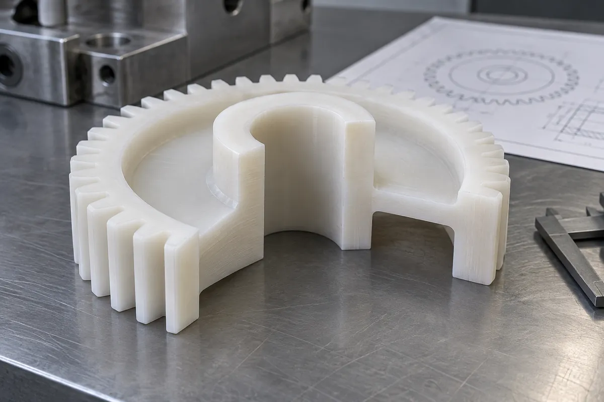
Ask what the hub is doing
The hub may support the bore, locate the gear axially or transfer load through a shaft interface. Name that function before changing its thickness for molding convenience. If the design contains a press fit, insert or D-bore, include the corresponding assembly requirements and the risks associated with altering the surrounding geometry.
Inspect the transition from hub to web and from web to rim. Review ribs and recesses on both faces, including whether the part is intentionally asymmetric. Changes intended to improve filling or cooling should be evaluated against the gear's stiffness and mounting function, not accepted solely because they make the part look more uniform.
Protolabs' molding-defect guidance discusses thickness and gate-related contributors to defects. A custom gear still needs its own review: a general molding recommendation does not define the correct hub thickness or guarantee a flat gear.
Review filling and cooling as a proposed process
Ask the tooling proposal to show the feed route, venting concept and ejection arrangement at a useful level. Note where flow divides around the bore or insert and rejoins. Discuss whether the resulting regions coincide with loaded or highly constrained features. These are engineering questions to investigate, not proof of a defect from a sketch.
If flow analysis is used, record the model revision, material data and assumptions. Protolabs describes analysis as a way to investigate gates, knit lines and trapped gas in its mold-flow overview. Predictions can guide a trial, but a colored result image is not a dimensional report or a measured wear result.
| Feature | Review together | Evidence needed later |
|---|---|---|
| Gate | Fill route, vestige, removal access and functional keep-out areas. | Actual molded and trimmed surface condition. |
| Hub and bore | Load transfer, wall transition, shaft fit and datum use. | Defined bore, location and assembly measurements. |
| Web and rim | Geometry, ribs, cooling concept and stiffness requirements. | Specified side-face and tooth-related inspection. |
| Ejection | Support, ejector locations and release sequence. | Sample evidence of acceptable shape and surface condition. |
Define warpage in terms you can inspect
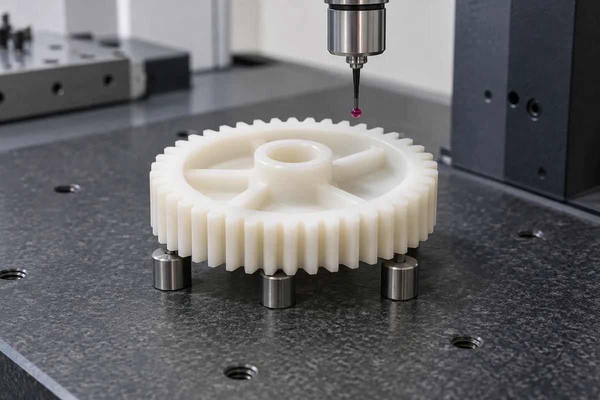
“No warpage” is not a measurement definition. Specify the relevant drawing characteristics and the condition under which they are checked. A side face, a bore axis and the tooth system may each have a different relationship to the assembly. Decide whether the part is measured free or under a defined restraint.
Keep support points and measurement alignment visible. Pressing a flexible gear flat against a plate may answer a different question from inspecting its free condition. If the assembly intentionally constrains the part, that can be relevant, but the required restraint should be documented rather than introduced informally to improve a reading.
Close changes using identified trial samples
When comparing a gate or geometry revision, retain the previous configuration and identify all changes. A different resin, gate and web thickness together form a new design/process combination. If the result improves, do not assign the improvement to one change without evidence that isolates it.
Review the samples with the gear inspection plan and the intended mating arrangement. Keep tool measurements separate from molded-part results. Tooling precision is useful evidence about the mold, but the buyer is approving the actual delivered gear and its agreed function.
End DFM with a controlled drawing and an open-items list. Each unresolved item should have an owner and an approval gate. That is a more practical deliverable than a broad promise of “zero distortion,” especially before representative samples exist.
Turn the review into a defined molding scope
Explore our custom injection-molded plastic gears and the related illustrative engineering study. Send the drawing revision, counterpart details, intended use and the decisions still open. Development samples and production approval should have separate, agreed deliverables.