
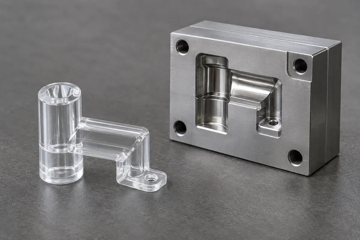
Product design illustrations. Final geometry, materials and acceptance criteria are project-specific.
A light pipe is a molded component with an optical job. The tool must fill, cool and release it, but a convenient witness mark can fall on a surface that determines how the indicator looks. Before choosing a gate or marking ejector locations, distinguish the entrance, guiding surfaces, exit and mechanical supports on the part drawing.
The question is not whether every surface can be made cosmetically flawless. It is which surfaces perform which function, what variation is acceptable, and how that will be checked on the actual assembly. Without that distinction, a quotation can include a polished part that still fails its viewing requirement.
Define surface zones before reviewing the tool
Identify the LED-facing entrance and visible exit separately. Record any intentional exit texture or diffusion feature. Mark the guiding surfaces and the areas that may contact a carrier. An entrance with a gate vestige, a guiding face with an ejection witness and a mounting foot with the same witness do not present the same risk.
Keep surface appearance separate from optical acceptance. A surface may look smooth under room light yet behave differently when illuminated in the final arrangement. Conversely, a deliberately textured exit can look less transparent while producing the intended indicator appearance. Do not convert the entire part into a single generic “high polish” requirement.
The VCC light-pipe technical article describes how geometry and interfaces influence the path of light. For a tooling review, the practical implication is to preserve a clear connection between each surface and its optical role. This is not evidence that a particular finish grade will satisfy a custom design.
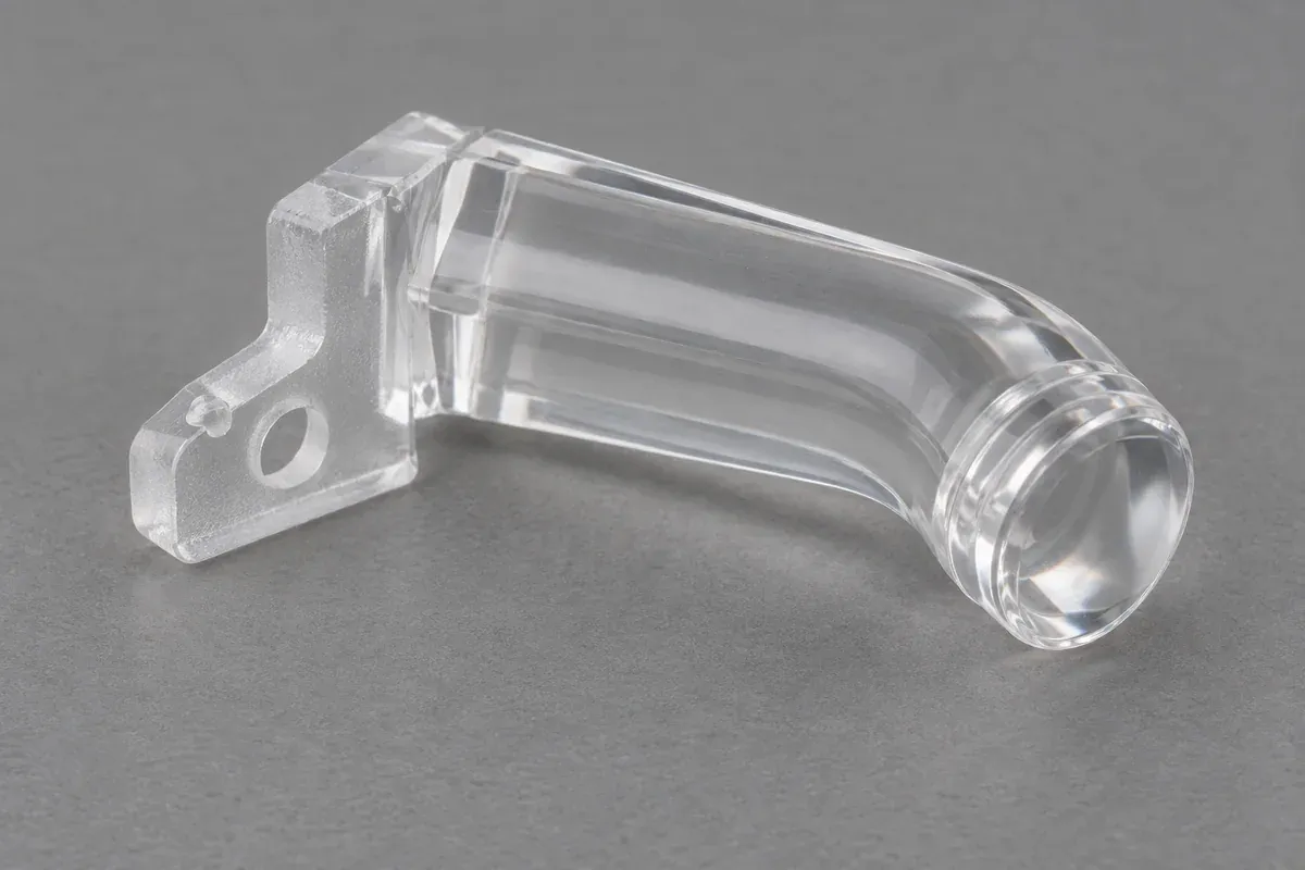
Evaluate the gate with the filling path
A gate on a nonvisible mounting feature can keep the visible exit clear, but its position still changes the filling path. Review thin sections, changes in thickness and flow that divides and rejoins. A gate location is not approved solely because its vestige is hidden after assembly.
Agree how the gate is separated and what remains. A trimming operation needs access and a defined result; it must not scratch nearby optical faces or distort a locating feature. If the proposal adds a tab, confirm whether the tab is part of the delivered component or removed before inspection.
Ask the tool designer to show the proposed gate and any relevant predicted flow behavior against the same part revision. Analysis can identify risks and support a trial plan. It should not be presented as a measured brightness result, especially when optical surfaces, exact material properties or source conditions are not represented.
| Feature | Define on the drawing | Check on samples |
|---|---|---|
| Gate | Permitted zone, separation method and remaining witness. | Vestige geometry, nearby surface condition and assembled function. |
| Parting line | Approved path and local mismatch or flash criteria. | Actual witness in the mounting and optical regions. |
| Ejector contact | Contact pads and surfaces unavailable for contact. | Local marks, distortion and damage after release. |
| Surface finish | Guiding, exit, entrance and mechanical zones. | Specified appearance plus optical evaluation under controlled conditions. |
Parting lines are local requirements
Follow the proposed mold split around the part. A seam crossing a mounting diameter can affect insertion, while one crossing the visible exit can change its appearance. Define the allowed local condition instead of applying a vague “no parting line” instruction to a molded component.
Where a shutoff creates an opening or mounting feature, discuss tool access, wear and the inspection method. A surface that is inaccessible after assembly may still need checking before assembly. Consider whether the proposed gauge can reach the characteristic without touching and damaging a neighboring optical face.
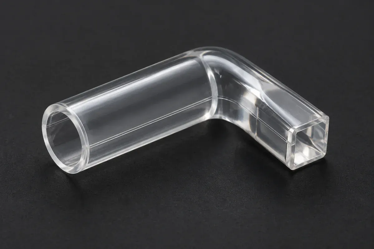
Give the part a credible release strategy
Ejection must move the cooled part off the tool without applying an unsuitable load to a narrow stem or unsupported optical feature. Review available pads, contact area, support and release direction. The location of a circular witness is only one aspect of the ejection decision.
Draft and retention geometry belong in this discussion. If the appearance design forbids a proposed taper, make the trade-off explicit before the mold is commissioned. Moving an ejector to an unobtrusive but fragile feature may exchange a visible mark for bending or damaged parts.
Keep packing and handling in the same quality plan. A good molded surface can be scratched by loose bulk packing or contact with a sharp divider. State which surfaces must remain protected and whether parts may touch each other in transit. Protection should follow the actual component geometry rather than a generic bag requirement.
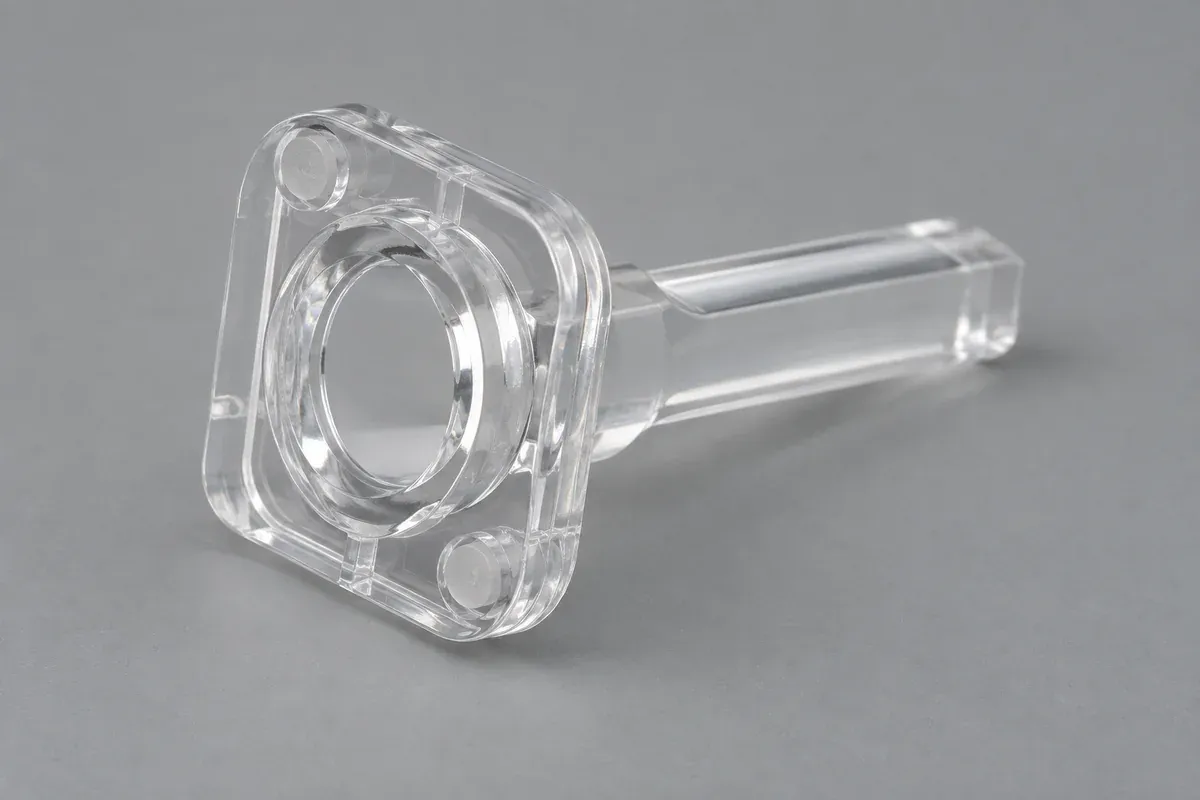
For first samples, tie visual observations to part identity, cavity and the agreed assembly. Use our light-pipe acceptance guide to separate visible molding witnesses from brightness and uniformity checks. The released tool plan should explain how functional zones are preserved and how remaining risks will be evaluated.
Turn the review into a defined molding scope
Explore our custom injection-molded LED light pipes and the related illustrative engineering study. Send the drawing revision, counterpart details, intended use and the decisions still open. Development samples and production approval should have separate, agreed deliverables.