
LSR Diaphragm: Thickness and Sealing Pilot Validation
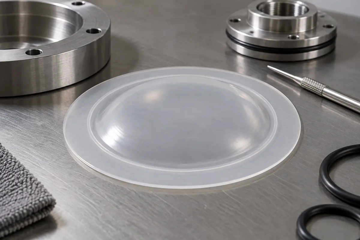
A small silicone diaphragm for a pump and valve assembly needed controlled membrane thickness and a less abrupt transition into its supported region. Early development had shown local cracking during cycling and a wider thickness spread than desired.
The owner confirmed that the actual project material was DuPont Liveo Q7-7840. The case reports component-level development observations; the material identity is not presented as certification of the finished component or medical equipment.
16 cavities
LSR molding tool
0.48–0.52 mm
Sampled membrane thickness
2,000 pieces
Pilot batch
Project background
Component, scope and current phase
| Application | Pump/valve diaphragm; customer equipment identity withheld |
|---|---|
| Actual material | DuPont Liveo Q7-7840 LSR; nominal 40 Shore A |
| Nominal geometry | 25 mm diameter, 0.5 mm active membrane and 1.5 mm intended stroke |
| Manufacturing | Sixteen-cavity LSR injection molding |
| Current phase | 2,000-piece pilot; endurance validation still running |
Engineering challenge
What the development work needed to resolve
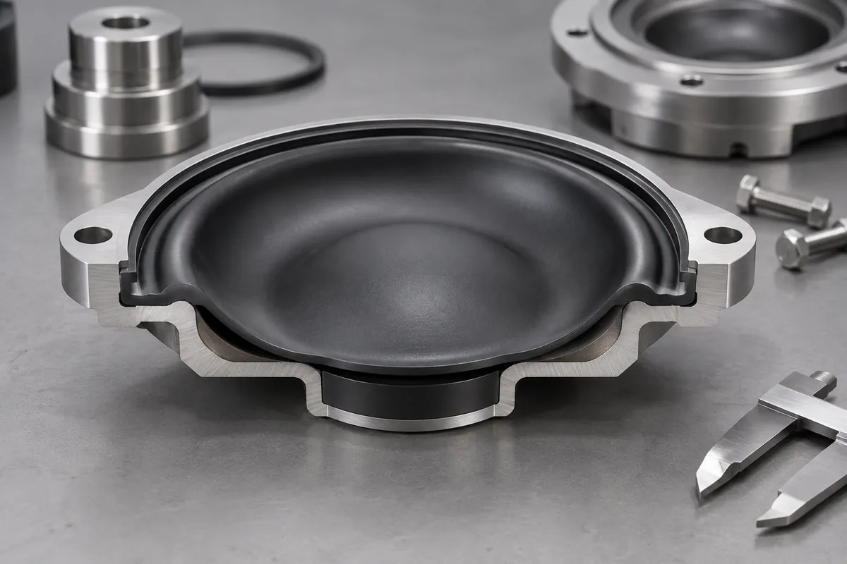
The initial record described a 0.45–0.55 mm membrane range and cracking near a transition during an earlier cycle trial. Thickness distribution, transition geometry and the assembled constraint therefore needed review together.
A successful short water-pressure check would answer only the sealing question at that condition. It could not close the separate endurance target or establish compatibility with every intended process fluid.
Manufacturing review
Changes and the verification approach
The development changes included a 0.3 mm transition radius and a gate-balance review. The case does not assign an unverified chemical explanation to process-temperature changes or calculate a life improvement from unmatched trial conditions.
Pilot membrane inspection covered 32 specimens, two from each of the 16 cavities, at five defined measurement locations. Keeping cavity and location information makes local variation visible instead of reducing the membrane to a single average thickness.
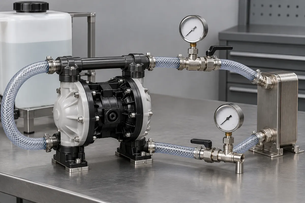
An assembled pump-head water-pressure check was recorded separately from hardness and fatigue testing. The ongoing cycle program retained its 500,000-cycle target as an open requirement rather than a completed result.
T0 · June 25
200 development pieces
T1 · July 20
500 pieces
Pilot · September 15
2,000 pieces
Recorded observations
Results with their sample and test boundaries
Each result below applies to the stated specimens and configuration. Development, pilot and production checks are not combined into a single pass rate.
These are owner-supplied project summaries, not independently certified test reports.
| Check | Samples and conditions | Recorded observation | Interpretation boundary |
|---|---|---|---|
| Membrane thickness | September 18 pilot sample; 32 parts, 16 cavities × two; five measurement locations | 0.48–0.52 mm | Against the project 0.50 ±0.03 mm requirement |
| Assembled water-pressure check | September 20; 50 specimens in pump assembly; 0.2 MPa for 60 seconds | No leakage reported during the hold | Specific short-duration assembled test, not a general pressure rating |
| Hardness | 20 sampled specimens | 38–42 Shore A | Project measurement summary |
| Fatigue checkpoint | 10 specimens; 1.5 mm stroke, 60 cycles/min | 200,000 cycles with no crack or leakage reported at the checkpoint | Interim result only; 500,000-cycle target remains open |
Release status
What is established and what remains open
As of October 6, the pilot remained under validation. The dimensional and short sealing results do not establish completion of fatigue, biological evaluation or finished-system qualification.
The actual material grade is confirmed by the owner, while original material and test reports were not attached for independent review. No ISO 10993 or finished-device approval statement is added.
Published anonymously with the project owner's permission. Original test reports and project photographs were not supplied for this publication review. Images are product design illustrations; no customer or supplier identity is displayed.
Related guides
Plan the next component review
- Flat vs Rolling Diaphragms: Match Motion and HousingCompare flat and rolling silicone diaphragms through stroke, support geometry, pressure direction and assembly constraints before choosing a molded construction.
- Silicone Diaphragm Thickness: Flexibility, Stroke and StressConnect silicone diaphragm thickness to flexible span, stroke, pressure and inspection. Avoid using a universal minimum wall or hardness as a fatigue prediction.
- Reinforced vs Unreinforced Rubber DiaphragmsCompare reinforced and unreinforced diaphragms using pressure support, motion, fluid exposure, fabric placement and manufacturing evidence—not strength labels alone.
- Diaphragm Clamping Beads and Housing InterfacesDesign a diaphragm bead and clamping housing around compression, location, edge transitions and assembly repeatability. Separate flange sealing from membrane function.
- Testing Silicone Diaphragm Fatigue Under Pressure CyclingPlan diaphragm fatigue and pressure-cycle tests with defined assemblies, waveforms, sample coverage and interim reporting. Keep endurance targets separate from measured results.
- Silicone Diaphragm Fluid Compatibility: Swell, Hardness and FunctionEvaluate silicone diaphragm fluid compatibility using exact compounds, complete exposure conditions and assembled-part testing. Separate material data from device approval.
Review your component and its mating assembly
Send the drawings, operating conditions, quantities and acceptance methods to define tooling, molding and inspection.