
Silicone Keypad: Force, Travel and Pilot Validation
A silicone keymat for an equipment control panel needed a more consistent response when installed over its membrane-switch stack. The project reviewed the flexible key web, bezel clearance and legend process together rather than treating the silicone part as an isolated cover.
The development record separates T1 response measurements from the later 1,000-piece pilot. Customer assembly evaluation and endurance testing remain open; the pilot is not described as completed mass-production validation.
8 cavities
Identified molding positions
4.2–5.8 N
T1 operating-force range
1,000 pieces
Separate pilot batch
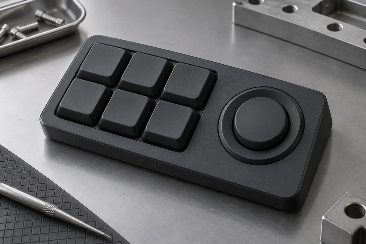
Project background
Component, scope and current phase
| Application | Equipment control-panel keymat with independent keys and a navigation feature |
|---|---|
| Material | WACKER ELASTOSIL LR 3003/40, black formulation; project nominal hardness 40 Shore A |
| Manufacturing | Eight-cavity LSR molding followed by an agreed laser-decoration operation |
| Mechanical target | 18 × 18 mm key outline, nominal 1.5 mm travel; response evaluated in the switch stack |
| Current phase | Pilot and customer assembly validation; no completed production-life claim |
Engineering challenge
What the development work needed to resolve
Early trials recorded an operating-force spread of 3–8 N against a 4–6 N target. Bezel interference and legend wear were also identified, so changing material hardness alone would not have addressed the full control-panel requirement.
The force measurement depends on the supporting switch and probe method. The project therefore needed a repeatable assembled test, plus a clear separation between mechanical response, contact behavior and decoration durability.
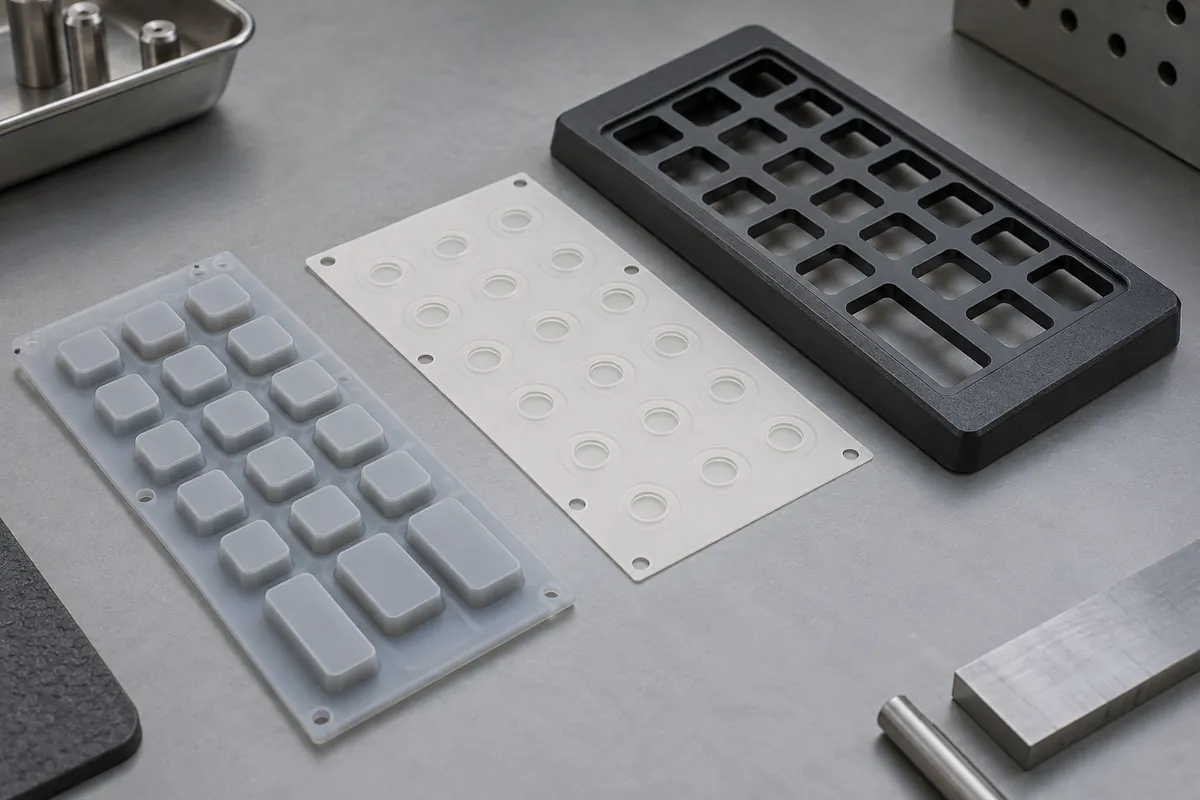
Manufacturing review
Changes and the verification approach
The recorded development work combined process adjustments with cavity and parting-region revisions and an assembly-clearance review. Laser decoration replaced the earlier legend route as a separately controlled operation. These were multiple changes; the case does not assign a percentage improvement to any single one.
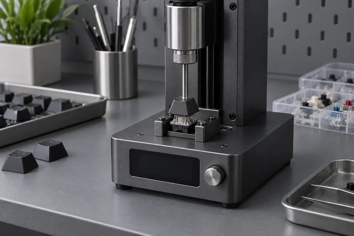
T1 response samples were identified across all eight cavities, with three specimens per cavity. The test used the membrane-switch assembly and a center probe moving at 5 mm/s. This gives the reported force range a defined configuration rather than presenting it as a material property.
The later pilot was used for additional dimensional checks and an ongoing actuation program. The life-test target remained separate from the completed checkpoint, preserving the distinction between a development observation and a qualified service-life statement.
T0 · August 20
50 development pieces
T1 · September 10
200 pieces; response sampling followed
Pilot · September 28
1,000 pieces for further evaluation
Recorded observations
Results with their sample and test boundaries
Each result below applies to the stated specimens and configuration. Development, pilot and production checks are not combined into a single pass rate.
These are owner-supplied project summaries, not independently certified test reports.
| Check | Samples and conditions | Recorded observation | Interpretation boundary |
|---|---|---|---|
| Operating response | T1; 24 parts, eight cavities × three; assembled switch stack, center probe at 5 mm/s | 4.2–5.8 N; travel 1.4–1.6 mm | Reported T1 observations, not a universal keypad force specification |
| Contact check | T1; 24 assembled specimens | 30–60 Ω | Project-reported contact result for this switch configuration |
| Pilot dimensions | 20 specimens | Key outline 17.95–18.05 mm; rise 0.75–0.85 mm | Sampled dimensional results, not full inspection of all 1,000 parts |
| Endurance checkpoint | 10 pilot specimens; 30 actuations/min | At 50,000 cycles: legends intact; reported force change below 0.5 N | Interim observation; the 100,000-cycle target was not yet completed |
Release status
What is established and what remains open
As of October 8, 2026, the 1,000-piece pilot remained in customer assembly validation. The supplied record does not establish completion of the 100,000-cycle program.
No equipment ingress rating, finished-device certification or lifetime guarantee is inferred from the material grade or the short-term response checks. The approved release requires the actual keymat, bezel, switch stack and decoration configuration.
Published anonymously with the project owner's permission. Original test reports and project photographs were not supplied for this publication review. Images are product design illustrations; no customer or supplier identity is displayed.
Related guides
Plan the next component review
- Silicone Keypad Design: Force, Travel and Tactile FeelSpecify silicone keypad actuation force, travel and tactile response together. Review the web, switch stack, support and sample measurement method.
- Carbon Pills vs Metal Domes for Silicone KeypadsCompare conductive carbon contacts and metal domes for silicone keypads using switching force, travel, board interfaces, resistance and assembly requirements.
- Backlit Silicone Keypads: Legends, Light Bleed and UniformityDesign a backlit silicone keypad around the light path, opaque barriers, legend process and assembled viewing conditions. Keep illumination and sealing tests separate.
- Silicone Keypads vs Membrane Keypads: Product Trade-OffsCompare silicone and membrane keypads using tactile response, profile, decoration, sealing interfaces and assembly cost. Choose for the intended equipment interface.
- Printed vs Laser-Etched Silicone Keypad LegendsCompare printed and laser-etched silicone keypad legends for contrast, backlighting, wear and process control. Specify the finished decoration stack and test exposure.
- LSR Injection vs Compression Molding for Custom KeypadsCompare LSR injection and compression molding for custom silicone keypads using tooling, geometry, decoration, handling and approval scope rather than volume alone.
Review your component and its mating assembly
Send the drawings, operating conditions, quantities and acceptance methods to define tooling, molding and inspection.