
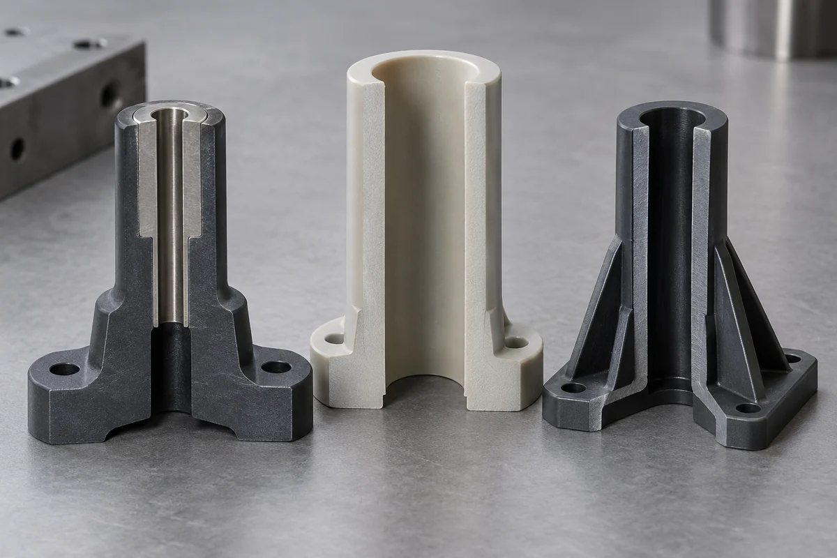
Product design illustrations. Final geometry, materials and acceptance criteria are project-specific.
A spacer needs enough material to support its assembly, but adding plastic everywhere is not automatically a stronger or more consistent design. Thick regions, abrupt transitions and poorly defined contact faces can create manufacturing or assembly concerns. The useful question is where material carries load and where it adds bulk without improving the function.
In this discussion, a hollow spacer has a deliberately cored interior or through-bore. A thick or solid-bodied support may still contain a screw hole, but it retains more material around it. Neither description establishes a load rating. Compare the proposed shapes using the actual fastening arrangement, material grade and acceptance requirements.
Start with the bearing surfaces
Identify the faces that establish the gap between components. Their contact area, flatness and position matter more than the appearance of the outer envelope. If a flange touches only a narrow edge of the mating part, increasing the outer diameter elsewhere may not improve the load path. Sketch the assembly section before adjusting wall thickness.
Keep gates, ejector witnesses and parting lines away from critical bearing zones where practical, and agree any permitted witness explicitly. A nominal overall height can be correct while a raised feature changes the assembled distance. This is why the drawing needs to distinguish a functional contact face from a general exterior surface.
Review thickness transitions rather than one isolated number
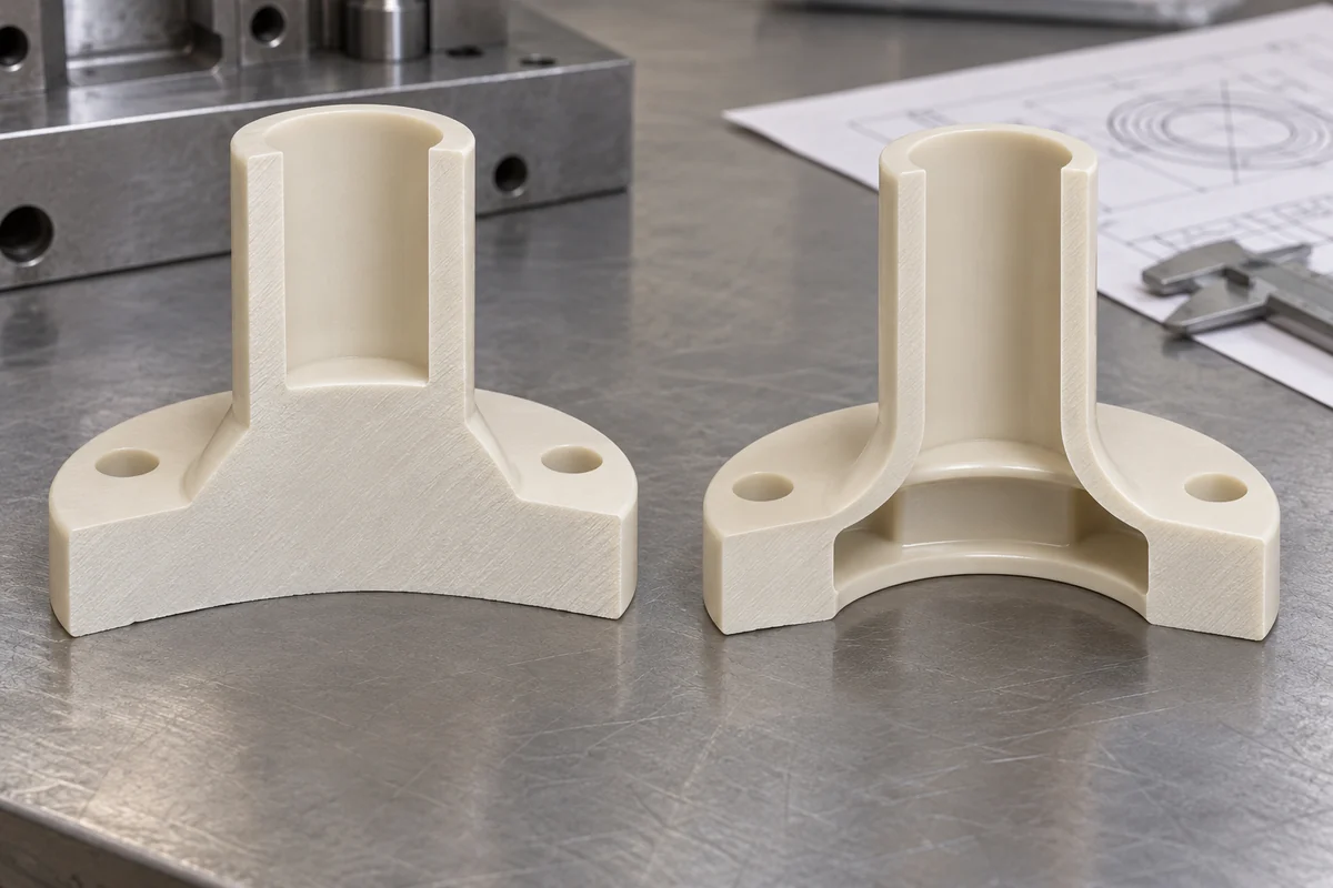
A thick base joined to a thinner stem deserves separate attention from a uniform sleeve. During DFM, review how those regions fill and cool, where the gate feeds the section and how the part releases. A revised transition may be more useful than increasing packing pressure to compensate for a geometry that remains difficult to mold consistently.
Protolabs' molded-part strengthening guidance discusses coring and ribs as alternatives to simply adding wall thickness. Apply the principle to the specific resin and shape rather than copying a universal rib ratio. Tooling access, appearance and the loads in the assembly all affect the final geometry.
The available bore size may limit how much a tubular spacer can be cored. A large internal opening can reduce the bearing area or leave too little material around a fastening feature. Evaluate both sides of that trade-off. A lighter section is useful only if the resulting part still supports its defined mechanical and dimensional duties.
Use ribs with a clear structural purpose
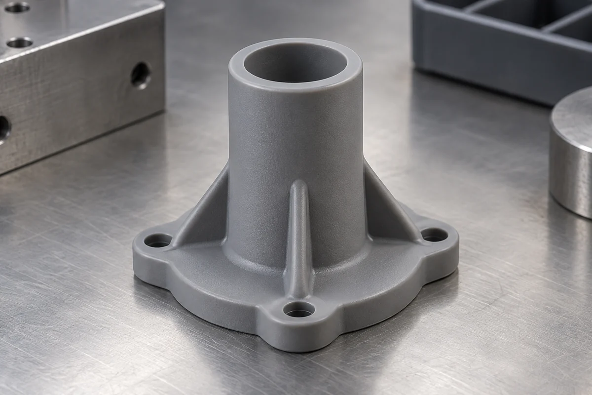
Ribs can connect a stem to a flange or support a thin wall, but their direction should relate to the load they resist. Decorative ribs add complexity without necessarily improving the relevant behavior. Determine whether the concern is lateral deflection, local bearing, installation damage or another failure mode before choosing the reinforcement layout.
Also review the rib roots and intersections. Several features meeting at one point may recreate a thick region that coring was intended to remove. Smooth transitions and an accessible molding direction need consideration together. If the part requires a side action or difficult core because of the rib arrangement, include that effect in the tooling quotation.
Keep mold release and inspection practical
Discuss draft on the surfaces that slide along the mold during ejection. A designer may want an apparently parallel exterior, while the toolmaker needs a reliable release strategy. Resolve that difference with explicit drawing references, especially when a tapered surface could be mistaken for a locating diameter or measured at the wrong height.
Make inspection access part of the review. A deeply recessed bearing face may be difficult to reach with an agreed instrument. A decorative rim may interfere with a height check. The spacer tolerance article describes why consistent contact points are necessary before dimensional results can be compared.
Validate the revised geometry in its assembly
Changing a thick support into a cored or ribbed form can alter the location and area of contact. Check the mating board or panel, fastener and washer again after the change. Do not carry over an earlier fit approval automatically if the revision changes the surfaces that determine installed height or receive compression.
Where a sustained load matters, assess the revised part under the relevant time and temperature conditions. A short fit check can identify interference, but it does not demonstrate resistance to long-term creep or loss of clamp force. Agree the test and the allowed movement before selecting the final design.
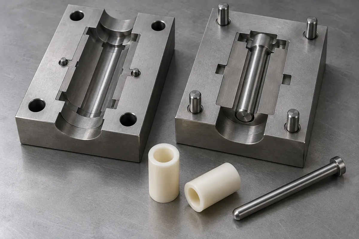
A useful DFM submission includes the part section, mating surfaces, expected load and the features that must remain unchanged. This allows a molding supplier to propose targeted coring or reinforcement without quietly altering the assembly. Record the accepted revision so the mold, sample report and recurring production inspection all refer to the same geometry.
Discuss your custom spacer
Explore our custom injection-molded plastic spacers and standoffs. Send the drawing revision, mating components, material requirements and expected quantities. FECISION can review the molding and sample-approval scope; application ratings and final acceptance must follow the agreed project requirements.