
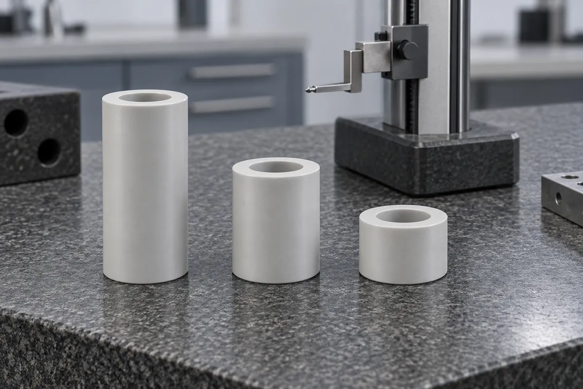
Product design illustrations. Final geometry, materials and acceptance criteria are project-specific.
When an assembly gap is wrong, tightening the spacer tolerance is an easy first reaction. It may also be an expensive one that leaves the real problem untouched. The gap can include the spacer, a washer, a panel, a board and the position of a mating feature. Unless that relationship is defined, a more precise spacer may still support the assembly at the wrong height.
Begin with the functional question: which two features must remain a specified distance apart, and in what assembly state? A connector alignment requirement is different from a minimum clearance under a board. The first can depend on the complete location chain; the second may be governed by one local feature or the lowest point of a bowed component.
Draw the chain between the functional features
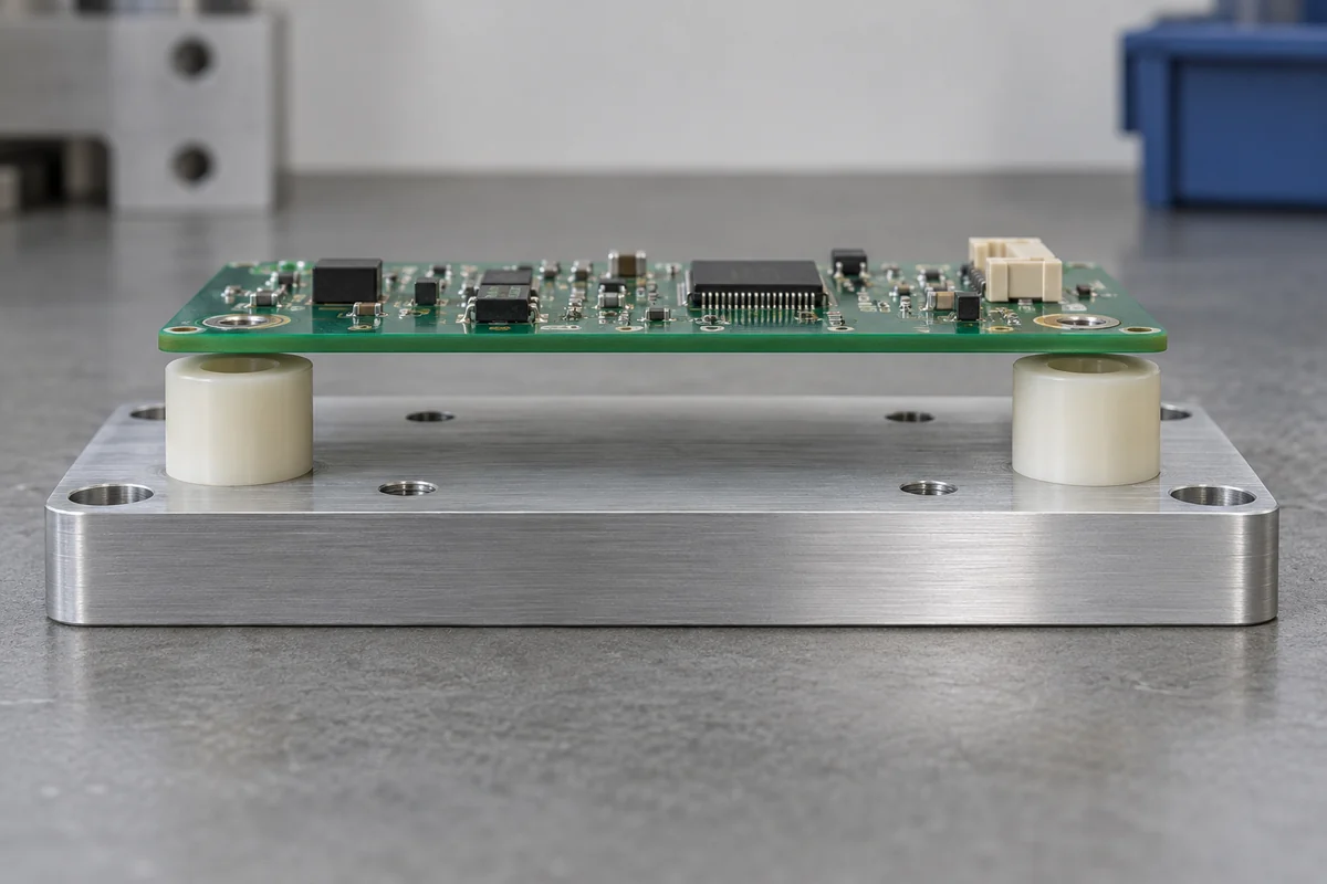
Make a simple section through the mounting point and follow the contact sequence. Identify the base datum, spacer lower face, spacer upper face and supported component. Add any washers, inserts or shoulders that actually set the location. Do not include a dimension merely because it appears near the assembly in the CAD model.
As a purely hypothetical arithmetic example, suppose a gap is the spacer height minus the thickness of an intervening panel. If those independent dimensions are specified as 12.00 ±0.10 mm and 1.60 ±0.10 mm, the nominal gap is 10.40 mm and a simple worst-case bound is ±0.20 mm. Those numbers are an illustration of the calculation, not a FECISION production tolerance or a customer result.
The example deliberately leaves out compression, flatness and thermal effects. A real stack should identify whether those effects belong in its model. Statistical stacking can be appropriate under justified assumptions, but it should not be used simply to obtain a smaller number when process distributions and dependencies are unknown.
Specify the faces that establish height
A spacer's overall envelope is not always its functional height. A molding witness, local boss, chamfer or flange can change where the counterpart sits. Mark the annular bearing surfaces and distinguish them from non-contact features. The drawing and measurement procedure should refer to the same surfaces used by the assembly.
Flatness and the relationship between end faces can also influence seating. A single reading across the highest points may not explain why the assembled board tilts. Decide how form and orientation will be checked where they affect function; do not assume that a tighter two-point length tolerance controls every aspect of the supporting surface.
The discussion of tolerances and molded-part dimensional behavior in the Delrin design guide is a useful reference starting point. Its legacy guidance is not a dimensional guarantee for an unrelated resin or mold. The proposed grade, part shape and actual measurement method still need a project-specific agreement.
Make the measuring method repeatable
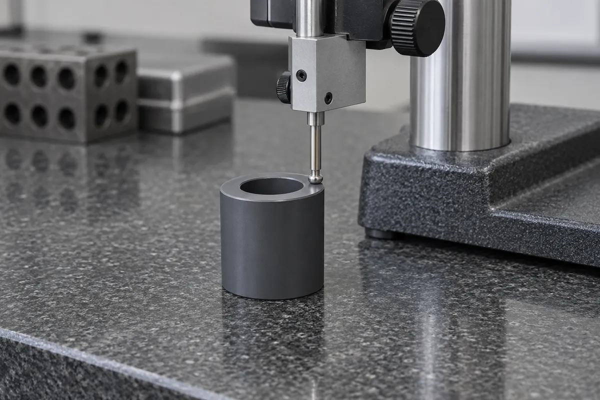
Write down how the sample is located and which surface the probe contacts. A height comparator on a clean datum plate may be suitable for one geometry, while a different part may need a fixture or a more detailed measurement program. Avoid placing the probe on the edge of a bore or a local witness when the drawing requires the bearing face.
Connect the inspection state to the material review. Record temperature, elapsed time and any agreed conditioning. If the drawing specifies a free-state dimension, do not clamp the sample hard enough to conceal its variation. If the acceptance requirement is assembled, specify the fastening conditions and counterpart configuration separately.
Look at each cavity before averaging the results
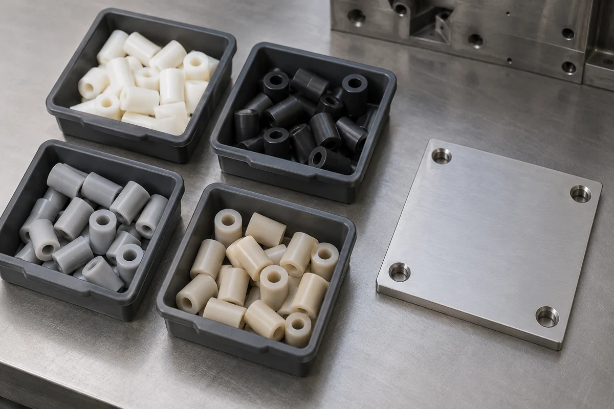
In a multi-cavity mold, combining every sample into a single average can hide a consistently different cavity. Keep the sample identity and cavity reference wherever practical. Review the spread as well as the center, and relate unusual readings to the tool, process and sample-handling record before choosing a corrective action.
A small first-article sample can establish that the inspected specimens meet the specified dimensions. It cannot by itself establish long-term process capability. If capability indices or an outgoing defect rate are required, agree the population, sampling and calculation basis before the supplier promises a number.
Allocate precision where it protects function
Return to the functional stack after the first samples. If one uncontrolled washer dominates the allowance, reducing the spacer variation alone is unlikely to resolve the assembly. Conversely, if spacer height is the dominant term, tooling or process changes may be a better investment than sorting assemblies after production.
Keep mold-release requirements in the same review. A draft angle proposed to release the outside wall may be harmless, while a change to a bearing face or locating shoulder may affect the stack. The spacer wall and coring guide discusses how geometry decisions should preserve the features that perform the spacing function.
Discuss your custom spacer
Explore our custom injection-molded plastic spacers and standoffs. Send the drawing revision, mating components, material requirements and expected quantities. FECISION can review the molding and sample-approval scope; application ratings and final acceptance must follow the agreed project requirements.