
PA66-GF33 PCB Support Spacer: From T0 Correction to Production
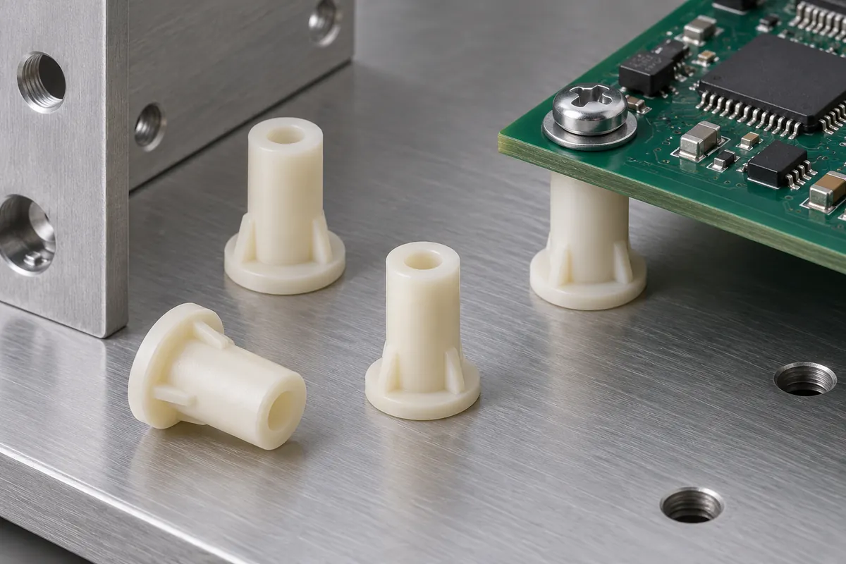
A small support spacer had to maintain the relationship between an industrial control board and its chassis. Early samples were undersize at the outside diameter and showed excessive end-face flatness error. The project combined a gate and section review with a revised packing setup before sample approval and recurring production.
This anonymized summary uses project records supplied and confirmed by FECISION. The results below describe this component and its recorded samples, not a general molding tolerance or performance guarantee.
Process
Plastic Injection Molding
Material
PA66-GF33 · Natural
Application
Industrial Control Electronics
Project Background
A defined gap between board and chassis
The spacer provided static separation and location between an industrial-control PCB and its mounting structure. The project brief described an operating environment of −20 to 70°C. That range was an application requirement, not an endurance-test result established by the dimensional inspections described here.
FECISION's scope included DFM, coordination of the tool design and manufacture, process-parameter review, first-article measurement and production inspection. Mold manufacture was assigned to a partner factory. The customer and supplier identities are omitted from this public summary.
DFM began on January 15, 2026. The development sequence recorded T0 sampling on February 28, T1 on March 10 and a 500-piece trial on March 18. The March 15 Revision B drawing formed the dimensional reference for subsequent approval; first-article approval was recorded on March 20.
Challenge
Separate fit, flatness and local appearance
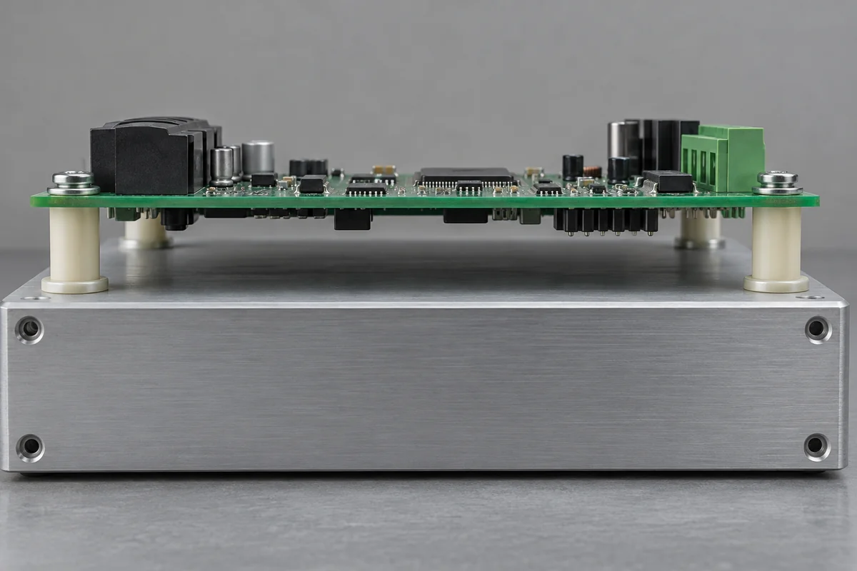
The drawing called for an 8.00 ± 0.05 mm outside diameter, a 4.20 ± 0.05 mm bore and a 12.00 ± 0.10 mm overall height. End-face flatness was limited to 0.05 mm. These requirements served different functions: location and clearance depended on the diameters, while the support height and face condition affected the installed relationship.
The T0 comparison summary recorded an outside diameter of 7.88 mm and flatness of 0.08 mm, both outside their stated limits. It also identified sink around a locally thick base section. The team therefore had more than one issue to address; a corrected diameter alone would not establish acceptable bearing-face condition or appearance.
Project notes identified packing and early gate freeze as contributors to the dimensional issue. They also called out a 2.5 mm base adjoining a thinner 1.2 mm wall. These observations guided the next trial. They should not be interpreted as proof that the same settings or geometry changes will resolve every glass-filled nylon spacer.
Engineering Response
Revise the feed path and the thick section together
The recorded corrections enlarged the gate from 0.8 to 1.0 mm, reduced the base section from 2.5 to 2.0 mm and introduced reinforcing ribs. The packing setup was revised to the project's recorded 600 bar and eight-second hold. These are historical project settings, not a recommended process window for other molds or machines.
The geometry change addressed local material distribution while the gate and packing review addressed feeding during the molding cycle. Because these changes were made together, the case does not attribute the entire dimensional improvement to one parameter. The revised samples were assessed against the required part and assembly characteristics.
The material is identified as Zytel 70G33L NC010, natural PA66 with 33% glass fiber, following the owner's clarification of the intake record. Resin selection was not substituted with a generic “nylon” designation. Any later change of grade, color formulation or reinforcement would need its own review against the controlled drawing and approval scope.
Recorded Results
Dimensions moved inside the specified limits
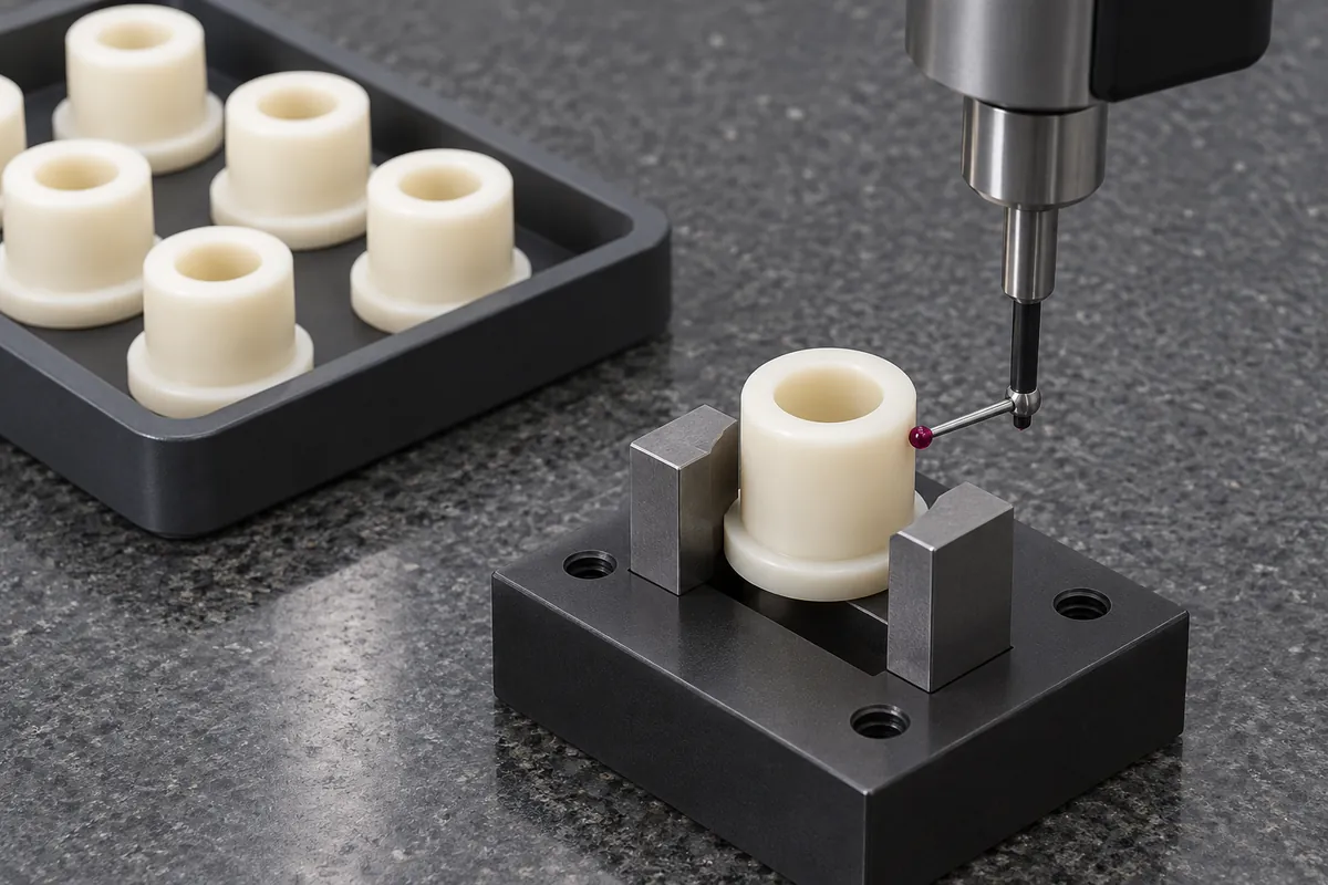
The project comparison recorded five samples at each of T0 and T1 under the same stated measurement conditions. Its summarized T1 figures were 8.02 mm for outside diameter and 0.03 mm for flatness. The summary does not identify those figures as a mean, minimum or maximum, so they are reproduced as recorded comparison values rather than a complete statistical distribution.
The separate inspection summary listed an outside-diameter range of 8.00–8.04 mm and a height range of 11.95–12.05 mm, measured at 23 ± 2°C. Those reported ranges fall within the respective drawing limits. The records provided for this page do not contain enough population data to calculate a process capability index or a long-term defect rate.
| Characteristic | Requirement | T0 record | T1 record |
|---|---|---|---|
| Outside diameter | 8.00 ± 0.05 mm | 7.88 mm | 8.02 mm |
| End-face flatness | ≤ 0.05 mm | 0.08 mm | 0.03 mm |
The assembly notes reported no board warpage during the documented fit check, with a locating-fit gap of 0.05–0.10 mm. Visual inspection found no sink in the examined samples and recorded a flash limit of 0.01 mm. These findings belong to their stated inspection scope; dimensional and visual acceptance do not by themselves demonstrate lifetime creep resistance, chemical compatibility or equipment safety compliance.
Production and Boundaries
Release the part without extending the claim
The project record states that recurring production began on April 10, 2026, with cumulative deliveries of 12,000 parts by September 2026. This is a project delivery figure, not a statement of general factory capacity. The record connects drawing approval, sample inspection and recurring supply for this specific support spacer.
Long-duration creep beyond 1,000 hours and chemical exposure were not established by the supplied project summary. The case therefore makes no lifetime, chemical-resistance or system insulation claim. Material classifications and customer release documentation are separate from the dimensional results presented here.
The practical lesson is to inspect the features that determine assembly function, address the related molding mechanisms and retain the boundary of the evidence. An acceptable diameter does not replace a flatness check; an approved sample does not establish every possible service condition. A future spacer project needs its own geometry, material, conditions and acceptance record.
Discuss Your PCB Support or Custom Spacer
Send the current drawing, mating components, material requirements and expected quantities. We can review a defined molding and sample-approval scope.
Request a QuoteRelated Products and Engineering Guides
Explore custom molded plastic spacers and standoffs or injection molding services.