
LSR Duckbill Valve: Flow and Sealing Validation
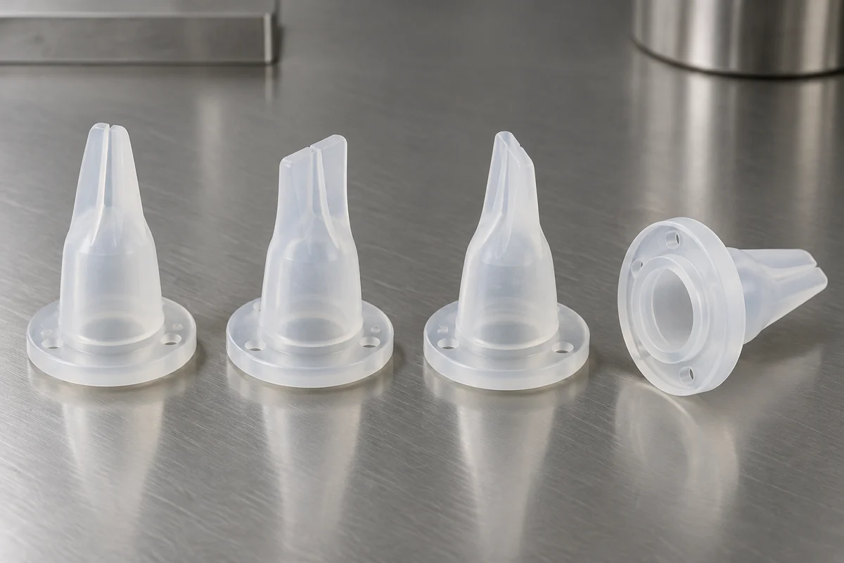
A small silicone duckbill valve was developed to control forward liquid flow and resist backflow. The project combined four-cavity LSR molding with a secondary slit and a finished-part coating, then evaluated opening pressure, reverse sealing and flow on the coated T2 samples.
The T2 functional checks and the later 100-piece pilot are separate records. The pilot remains under validation and has not been released as mass-production supply.
Process
Four-cavity LSR molding
T2 Checks
60 parts · 20 flow samples
Project Status
Pilot validation ongoing
Project Overview
Define a finished valve, not only a molded shape
The project concerns a one-way component intended for a medical-equipment fluid path. Its functional development does not establish approval or suitability of a completed medical device. The public material description is limited to LSR with nominal Shore A 40; material-grade and biological-evaluation claims are not made here.
FECISION's recorded work covered DFM, mold-design and process review, and component opening, reverse-sealing and flow tests. Mold manufacture was assigned to an anonymous partner. Customer and supplier identities are withheld.
Development began in May 2026, with T0 in July, T2 in August and a 100-piece pilot in September. These stages are not combined into a delivered production quantity. Customer validation remains open.
Confirmed project scope
| Application | One-way liquid-flow component under development for equipment integration |
|---|---|
| Material | Liquid silicone rubber, nominal Shore A 40 |
| Manufacturing | Four-cavity LSR molding, post-slitting and finished-part Parylene coating |
| Project roles | FECISION: DFM, tool/process review and component testing; anonymous partner: mold manufacture |
| T2 batch | 60 pieces, August 2026 |
| Pilot status | 100 pieces, September 2026; validation ongoing, not mass production |
Manufacturing Challenge
Control the lips and the opening formation
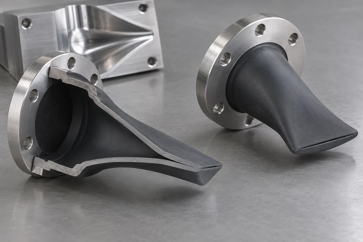
The early trial record described uneven lip thickness, sticking at the opening and flash affecting lip contact. These were different observations requiring a combined geometry, tooling and finishing review, rather than a single dimensional check.
The documented response included a revised core construction and parting-interface review. The final confirmed opening route was post-slitting: the valve was molded with a closed tip, then located in a dedicated fixture for a slit specified at 2.0 ± 0.1 mm.
That slit specification replaces the earlier intake value. It is a project-specific dimension, not a general recommendation for another valve. Lip geometry and opening formation still need evaluation against the intended housing and fluid conditions.
Finishing Sequence
Test the part after the agreed surface treatment
The owner confirmed that Parylene was applied to the silicone component after slitting, not to the mold. The reported coating thickness was 1–3 μm. The treatment was introduced with an anti-sticking objective; this case does not isolate or quantify the coating's individual contribution to performance.
The T2 opening, reverse-sealing and flow results below were all measured after slitting and coating. Measurements of unfinished or uncoated samples are not substituted for these results. The accepted test state therefore includes both molding and the subsequent finishing sequence.
No claim is made that the coating establishes chemical compatibility, sterility or biological safety. Those questions require evidence for the finished configuration and the specific intended use. The coating's reported thickness is not presented as a transferable process specification for other projects.
Recorded Results
Keep T2 functional checks separate from pilot yield
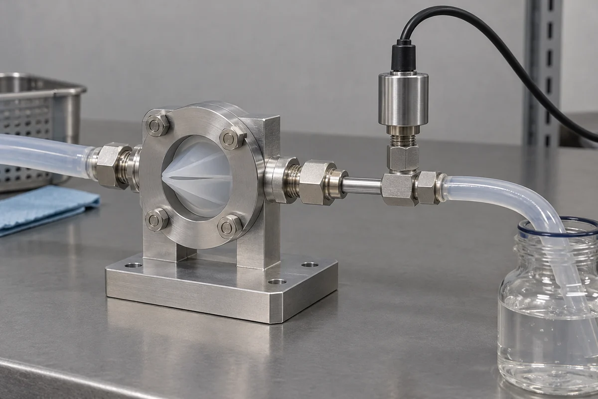
All 60 T2 parts underwent the opening-pressure check, with a reported range of 0.9–1.4 kPa. The same T2 population was fully checked for reverse sealing at 25 kPa for 1 minute, with no leakage reported during that hold.
Forward flow was a separate sample of 20 T2 pieces. The latest confirmed condition was 10 kPa differential pressure, with results of 620–780 mL/min. This is not a flow result at 5 kPa and does not establish compliance with a requirement at that different pressure.
For the later 100-piece pilot, appearance and dimensions were fully inspected and 98 pieces were accepted overall. Two pieces were rejected for excessive flash. Performance checks on that pilot were sampled, so its 98/100 outcome is not a full-inspection functional pass rate.
| Check | Condition | Reported observation | Population and limit |
|---|---|---|---|
| Opening pressure | Finished, coated T2 valves; forward-pressure test | 0.9–1.4 kPa | All 60 T2 parts; reported within the agreed opening range |
| Reverse sealing | 25 kPa held for 1 minute | No leakage reported during the hold | All 60 T2 parts; not a lifetime or unlimited-pressure rating |
| Forward flow | 10 kPa differential pressure; saline test medium | 620–780 mL/min | 20 T2 specimens sampled; not all 60 pieces |
| Pilot acceptance | Separate 100-piece September pilot; appearance and dimensions fully checked | 98 of 100 accepted overall | Two rejected for excessive flash; performance was sampled, not fully inspected |
Successful results among the tested specimens are not combined into one whole-project performance percentage. The reverse-sealing observation is limited to its pressure and duration; no instrument detection limit or long-term leakage rate is inferred from the available summary.
Validation Still Open
Complete application evidence before production release
The supplied record leaves extended pressure cycling, sterilization effects and compatibility with fluids beyond saline unresolved. The reported component checks do not qualify the valve for every drug solution, a different gas application or a higher-pressure circuit.
This anonymous case is based on real project records confirmed by the owner. Original test reports and project photographs are not reproduced here. The product design illustrations explain geometry and test concepts; they are not evidence of the measured results.
The next release decision needs the final drawing and finished-state process, the agreed fluid and functional requirements, and the remaining customer validation. Changes to the material, slit, coating or housing should be reviewed before earlier sample results are reused.
Related Guides
Plan a custom valve review
- Custom Silicone Duckbill Valves: What to Include in an RFQSpecify a custom silicone duckbill valve with housing geometry, fluid conditions, opening pressure, backflow testing and defined finishing requirements.
- Duckbill Valve Cracking Pressure: Specify the Test ConditionsDefine duckbill valve cracking pressure separately from operating flow and resealing. Review pressure taps, wetting, ramp method and finished-part condition.
- Duckbill Valve Backflow Tests: Separate Part and Fixture LeaksPlan a duckbill valve reverse-leakage test with defined fluid, pressure, hold time, detection limit and fixture checks. Keep sample counts and claims aligned.
- Duckbill vs Umbrella Valves: Compare the Housing and Flow PathCompare duckbill and umbrella check valves by sealing interface, housing space, mounting, opening behavior and validation before choosing custom tooling.
- LSR Duckbill Valve Lips and Slits: A Manufacturing ReviewReview LSR duckbill lip geometry, molding, post-slitting and surface finishing as one controlled process. Define inspection without assuming functional results.
- Silicone Duckbill Materials: Post-Cure and Evidence ReviewChoose silicone valve materials with grade-specific information, controlled post-curing and finished-part tests. Separate material data from device approval.
Review your valve and housing together
Send the drawings, fluid conditions and acceptance methods to define tooling, molding, finishing and component inspection.