
PPS Liquid-Cooling Manifold: Trial Validation
A glass-filled PPS distribution manifold needed a more consistent internal wall, cleaner channel intersections and a controlled sealing surface before it could move into system validation.
This anonymized case follows the owner-confirmed tooling and trial records. The project remains in system validation; the reported component checks do not establish series-production approval or long-term service life.
Process
PPS Injection Molding
Component
Fluid Distribution Body
Stage
System Validation
Project Overview
Develop the molded body within a defined cooling circuit
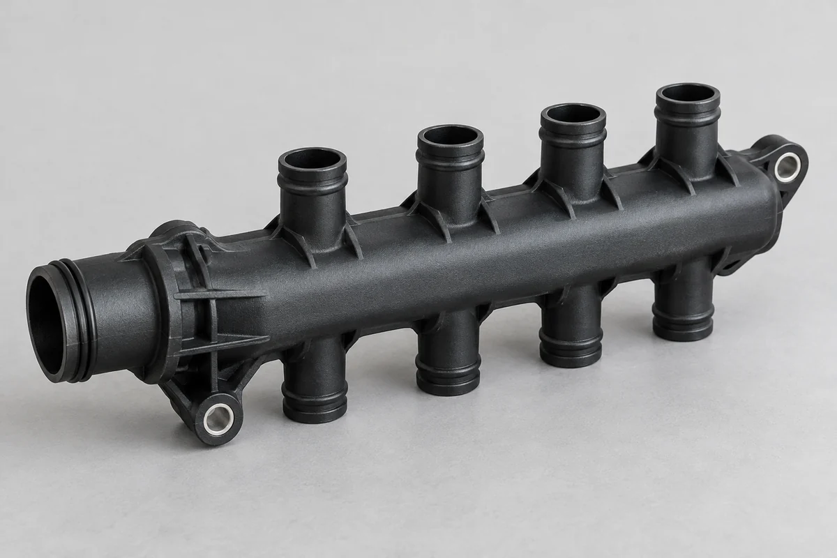
The manifold distributes and collects coolant in a server liquid-cooling unit. The project specified a glass-filled PPS body with multiple outlet interfaces and an internal channel. Its intended fluid, temperature and pressure conditions guided the engineering review; they were requirements to validate, not ratings established simply by selecting PPS.
FECISION's recorded scope covered DFM, review of the mold and core arrangement, process development, dimensional inspection and component pressure checks. A partner factory manufactured the mold. Complete-system validation remained a separate project stage.
Project scope
| Application | Coolant distribution and collection in a server liquid-cooling unit |
|---|---|
| Material | PPS with 40% glass fiber; project designation Celanese Fortron 1140L4 BK |
| Tool | Two cavities, hot-runner feed with side gates and eight slides |
| Drawing | Revision B, June 20, 2026 |
| Intended duty | Ethylene-glycol/water circuit; project requirements of 1.0 MPa and 5–55°C, not a validated service rating |
| Current stage | 50-part system-validation program; series-production approval remains open |
| Project roles | FECISION: DFM, tool review, molding development and component checks; partner factory: mold manufacture |
Manufacturing Challenge
The hidden channel affected both wall consistency and sealing
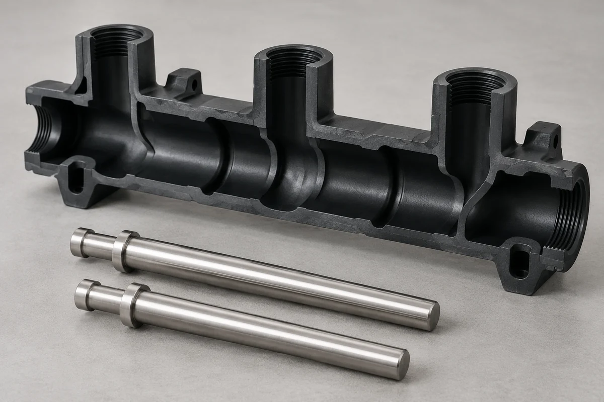
The T0 record described core offset and uneven local walls, with opposing regions reported at approximately 0.8 and 1.8 mm. The team associated the variation with the long internal core's support and location. These observations motivated the tool review; they are not a universal wall-thickness recommendation.
The same trial also identified flash at an internal core joint and a rough sealing surface after machining the glass-filled material. Those were separate concerns: improving the channel's location would not, by itself, close the flash or sealing-surface issues.
The earlier T0 lot contained 20 parts and did not complete the later pressure-check program. It therefore provides no comparable full-test baseline for calculating a leakage-reduction percentage. The subsequent T2 population must remain distinct from that early development lot.
Engineering Response
Support the core and form the seal face in the tool
The recorded changes added guiding and support at both ends of the core and refined the fit at the core joint. The intent was to control the channel position and reduce the opportunity for internal flash. Trial parts, rather than the tool-change description alone, were then used to assess the revised condition.
The seal-face strategy also changed. Instead of relying on the earlier post-machined surface, the revised route formed the sealing face directly against a polished tool surface. That made the molded surface and its flatness part of the trial review. This project-specific decision does not mean every reinforced-plastic seal face should avoid machining.
The material was recorded as Celanese Fortron 1140L4 BK, a 40% glass-filled PPS project specification. The T2 trial took place on June 28, 2026, against the revised drawing. Material identification, dimensions and pressure checks were kept as distinct pieces of evidence rather than combined into a general claim of qualification.
Recorded Results
Report the T2 check without turning it into a lifetime rating
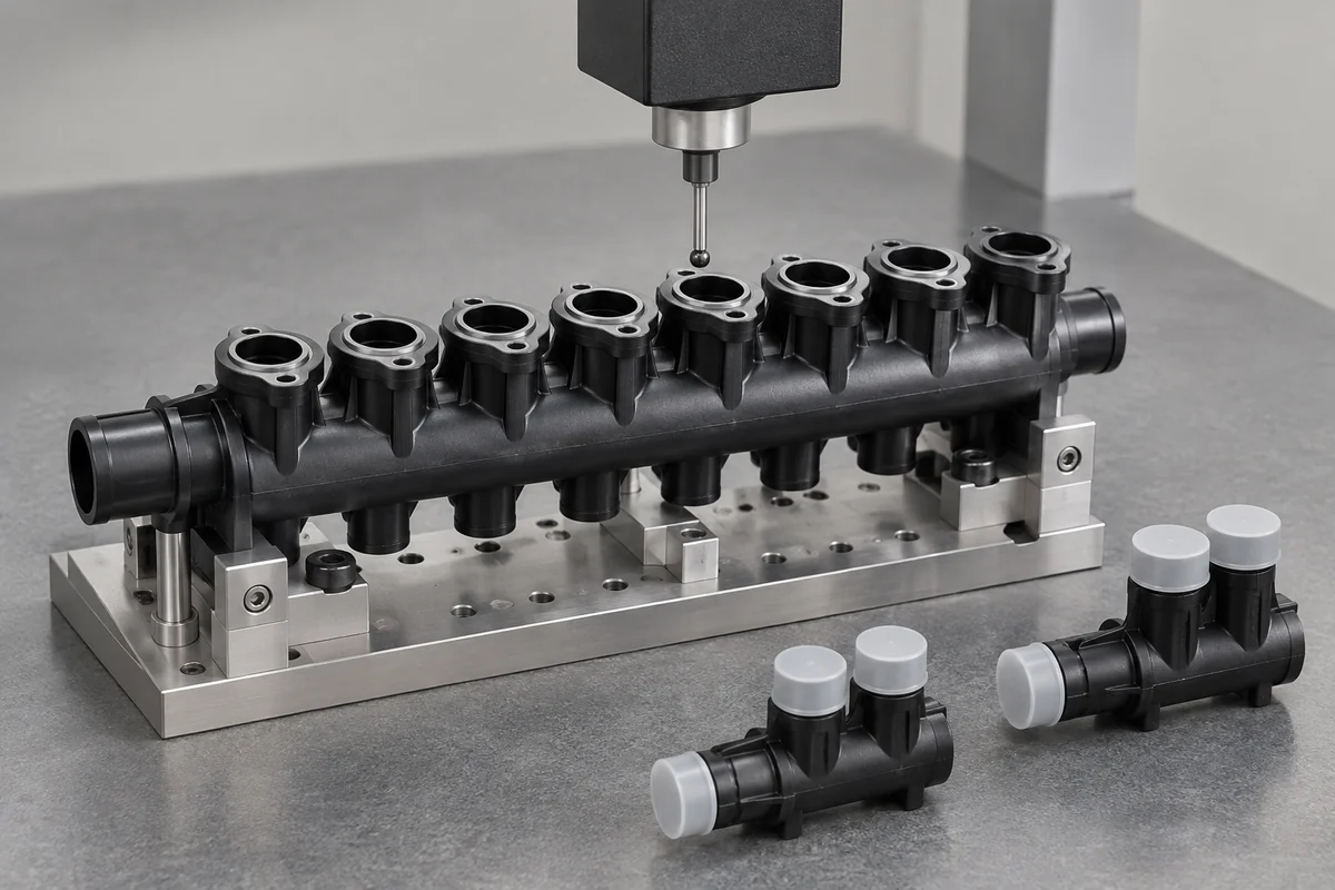
The owner confirmed that all 50 T2 parts underwent a water-pressure hold at 1.5 MPa for 5 minutes and were reported to pass, with no leakage observed in that check. These are project-recorded observations, not an independently verified leak-rate measurement or a guarantee of zero leakage under other conditions.
The supplied dimensional summary also reported outlet position and sealing-face flatness within their stated limits. The underlying reports are not reproduced here. The test procedure, instrument information and detection sensitivity would need to accompany any independent review of the pressure-check result.
| Characteristic | Recorded requirement | Reported result | Evidence boundary |
|---|---|---|---|
| Outlet position | ≤ 0.15 mm | 0.08–0.12 mm | CMM relative to the defined project datums |
| Sealing-face flatness | ≤ 0.05 mm | 0.02–0.04 mm | Project flatness inspection record |
| T2 water-pressure hold | 1.5 MPa for 5 minutes | 50 of 50 parts reported to pass; no leakage observed in that check | Owner-confirmed summary; not a calibrated leak-rate or lifetime result |
A later 50-part system-validation program began in July 2026 and remains open according to the owner's current confirmation. Its quantity is not added to T2 to claim a production-delivery total. No series-production release is claimed in this case.
Scope and Next Validation
Keep component improvement separate from system approval
Long-duration pressure exposure, thermal cycling and operation in the complete cooling circuit remain validation tasks. A brief component pressure hold does not establish creep resistance, fatigue life, coolant aging performance or system reliability. Those decisions need evidence matched to the intended service conditions.
This anonymized summary uses project information supplied and confirmed by FECISION for public use. Original project photographs and inspection reports are not reproduced. The supporting images are product design illustrations, not records of test results or delivered customer parts.
The useful engineering lesson is to address channel support, internal joints and seal-surface formation together while checking their outcomes separately. A more consistent molded body can be ready for the next validation stage without yet being approved for repeat production.
Related Engineering Guides
Prepare your own fluid-manifold review
Review the manifold with its complete set of interfaces.
Send the controlled drawing, fluid conditions, mating parts and component acceptance requirements.
Request a Quote