
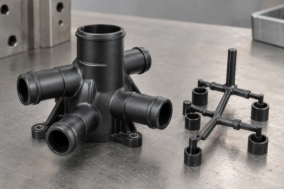
Product design illustrations. Final geometry, materials and acceptance criteria are project-specific.
A manifold's gate location affects more than where the runner is removed. Polymer must travel around channel cores, port openings and other features before the cavity fills. Where the flow divides and meets again, the resulting region deserves attention if it sits in the fluid boundary or near an assembly load.
The aim is not to demand a drawing with no weld lines anywhere. It is to understand where they are likely to occur, why those locations matter and what evidence is needed. A barely visible line may still require a functional review, while a visible mark in a noncritical region may be primarily an appearance concern.
Map the product's sensitive regions before placing a gate
Identify port roots, seal lands, mounting loads, thin walls and channel intersections on the controlled model. Explain which surfaces may carry a gate witness and which must remain free of trimming damage. The filling proposal should be evaluated against these functional requirements rather than only the convenience of reaching the cavity.
Protolabs' gate-design guidance describes the trade-off between gate choices, filling and the remaining witness. For a fluid component, that trade-off also needs the customer's sealing and assembly constraints. A trim location that is acceptable on an outer wall may be unsuitable on a mating land.
Ask where separated flows will meet
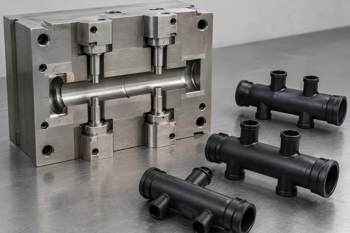
Protolabs' knit-line explanation relates meeting regions to flow around cores and to multiple gates. It also distinguishes changes in location from changes in appearance. Use that distinction when reviewing a manifold: improving how a line looks is not the same decision as moving it away from a critical load path.
Review the expected pattern with the selected resin and geometry. A simulation can help compare proposals, but the inputs and assumptions should remain visible. It is not a substitute for checking the actual molded configuration. If a design revision changes a port or wall region, revisit the filling assessment instead of treating an old image as current evidence.
Discuss gate count and venting together
Celanese's Fortron design guidance connects gate layout with flow continuity and recommends reviewing weld locations and venting. Apply the current grade-specific recommendations with the mold supplier. Do not copy a vent dimension or machine setting from an unrelated example and present it as a universal recipe for every glass-filled manifold.
Adding a gate can change filling length and the meeting pattern. It may also introduce another witness or require different tooling and process control. Reducing gate count can simplify one aspect while making another harder. Compare these effects against the actual component requirements rather than assuming that more gates or fewer gates must always be better.
Use trials to check the proposed explanation
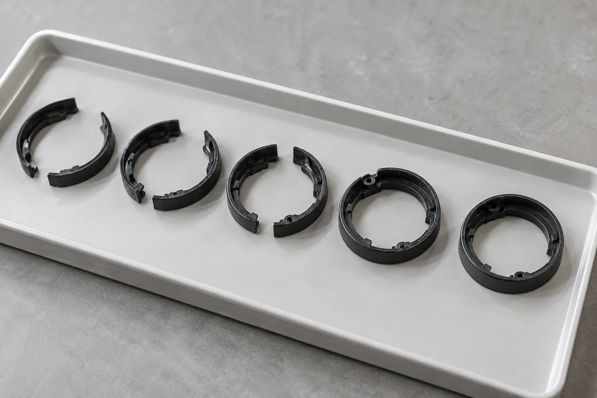
Plan the observations before the trial. Where appropriate, the molding team can examine controlled short-shot samples, surface features and the relation between a meeting region and a critical interface. Record the cavity, material, tool revision and trial conditions. Without this identity, a useful sample can become only an interesting object in a photograph.
Do not infer pressure capability from an intact-looking port. Decide which subsequent tests are needed to evaluate the relevant concern, including the intended conditioning and assembly state. The manifold test-plan guide separates a screening check from proof testing and longer-term qualification. None should be silently substituted for the others.
If several changes are made together, describe the combined configuration honestly. A gate relocation, material change and new temperature profile may produce a better result, but that does not prove which change contributed most. Retain the baseline and revised evidence without inventing a universal improvement percentage from a small development trial.
Protect the accepted configuration through later changes
Gate trimming and inspection should be defined for the released part. Mark the permissible witness area and the surfaces that must not be damaged. For an internal fluid path, explain how loose trimming debris or inaccessible flash will be addressed. External appearance alone cannot establish the cleanliness of the connected passages.
Keep the gate and core review connected. A different filling balance can matter to the support of a long channel core, while a core modification can change the flow path. The core-shift guide explains why wall distribution should be measured rather than inferred from an acceptable outside envelope.
Finally, specify what would trigger another review: a changed resin grade, a tool repair, a new cavity or a revised fitting interface may alter the accepted assumptions. A strong development record does more than show that one sample filled. It connects the filling proposal, observed parts and required validation to the configuration being supplied.
Discuss your molded fluid component
Explore our custom injection-molded fluid manifolds and the PPS liquid-cooling manifold trial case. Send the controlled drawing, mating interfaces, fluid conditions and acceptance requirements. Tooling, sample inspection and system qualification should have separately agreed deliverables.