
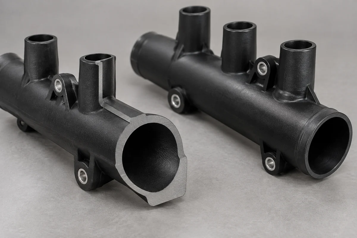
Product design illustrations. Final geometry, materials and acceptance criteria are project-specific.
A molded manifold can have acceptable outer dimensions while its internal channel lies too close to one wall. Inspecting only the outside envelope will not reveal that relationship. When a long core moves during filling, or its actual position differs from the design, the resulting wall distribution can matter more than the visual quality of the external surface.
Core shift is one possible explanation, not a diagnosis to assign from a single photograph. Tool geometry, fit, molding behavior and the way a part is sectioned or measured should be considered together. The purpose of the investigation is to locate the source of the variation before changing the process or approving a tool modification.
Compare the internal and external geometry in one reference
Identify the wall region that affects function and the datums that locate it. A bore diameter alone cannot show whether the bore is centered within the external body. Plan a measurement that relates both surfaces. Where a cut section is used, record its location and orientation so that another sample can be compared meaningfully.
Check that the preparation method has not distorted the specimen or removed the feature of interest. A convenient end section may miss the thinnest region farther along the channel. If hidden geometry requires another inspection method, agree its resolution and coverage rather than assuming that a visually attractive image is a complete dimensional result.
Trace how the core is located and supported
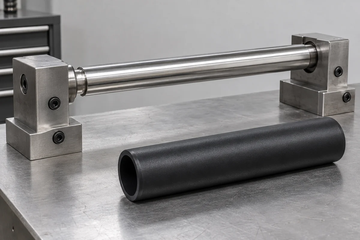
Review the tool's locating features, support spans, assembly clearances and condition. Ask which features establish the channel position and which only guide motion. A core that is well located when the mold is open still needs to maintain its intended relationship during the molding cycle. Tool-room checks and part measurements answer complementary questions.
Extra support may require a change to the channel or a new access feature. That can help the tooling while creating a closure or seal obligation in the product. Evaluate this trade-off with the component designer. A support decision should not quietly add another potential leak path without a corresponding change to the drawing and acceptance plan.
Review filling loads without relying on one adjustment
Discuss gate arrangement and how the polymer reaches the two sides of the core. An unbalanced filling pattern may be relevant to displacement, but increasing or decreasing a machine setting alone does not establish the cause. Compare controlled trials with the tooling condition and sample identity recorded, including which cavity produced each part.
Separate the evidence for core movement from dimensional changes associated with cooling and material behavior. These mechanisms can occur together. A process change that reduces an apparent offset may also change shrinkage or create a different defect. Confirm the intended geometry and the other critical features before calling the revised setting a solution.
Use the sample sequence to test the explanation
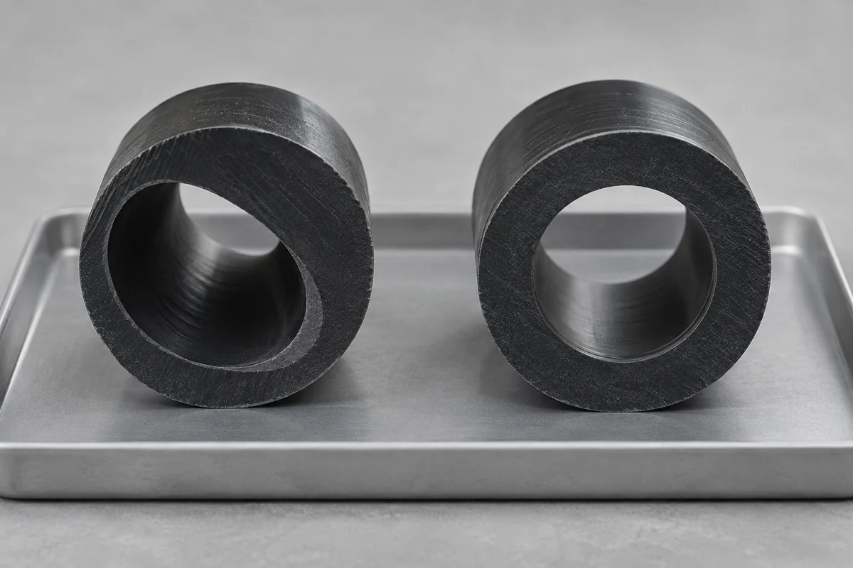
Inspect samples from more than one point in the trial where relevant. A first stable-looking part may not represent the later thermal state of the tool. Keep cavity identity, trial stage and measurement location attached to each observation. If the pattern changes through a run, that information is useful when deciding which mechanism to investigate next.
When modifying a locator or support, describe exactly what changed. Avoid combining several undocumented changes and then assigning the outcome to the most convenient explanation. It may still be necessary to change multiple items, but the report should distinguish an observed improvement from proof that one isolated factor caused it.
The filling and weld-line review should stay connected to this work. A new gate intended to balance loading can relocate a flow-front meeting region. That revised region may need its own assessment if it moves into a loaded port or another critical part of the fluid boundary.
Release a measured condition rather than a tool assumption
After corrective work, check the relevant wall distribution, port location and sealing surfaces on the agreed specimens. Preserve drawing and tool revisions so that the inspected geometry remains traceable. The fact that the tool was modified is not itself evidence that every product characteristic now meets its requirement.
Dimensional approval and pressure-related evaluation should be separate decisions. A more uniform wall is useful geometry evidence, but it does not establish a working-pressure rating or long-term life. Define the necessary component and system checks with the responsible engineering team and record what remains open after the dimensional review.
For repeat supply, agree how the risk will be monitored without pretending that every hidden surface can be checked by a quick external gauge. The plan may combine tool maintenance, process records and defined inspection sampling. Its scope should follow the actual feature and failure concern, with changes triggering a review of the accepted evidence.
Discuss your molded fluid component
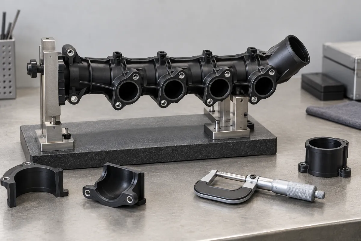
Explore our custom injection-molded fluid manifolds and the PPS liquid-cooling manifold trial case. Send the controlled drawing, mating interfaces, fluid conditions and acceptance requirements. Tooling, sample inspection and system qualification should have separately agreed deliverables.