
POM Hose Barb: Dimensional and Retention Review
An eight-cavity POM hose-barb program needed a cleaner tube-contact profile and more consistent retaining geometry. The development review connected tool changes with cavity-resolved dimensions and a defined PU-tube pull-off check.
The confirmed T1 evaluation covered 24 assemblies across all eight cavities. Production deliveries subsequently reached 85,000 pieces through September 2026. This case reports the connection and test conditions behind those figures.
Process
POM Injection Molding
T1 Coverage
24 parts · 8 cavities
Your Connection
Custom Hose Barb Fittings
Project Overview
Develop the fitting around a specified PU tube
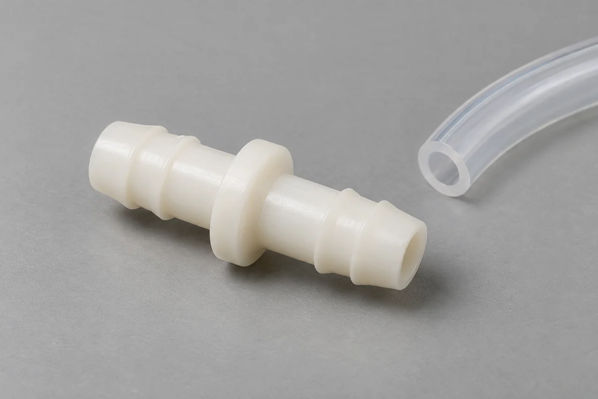
The component connected flexible tubing within pneumatic equipment. Its drawing specified a 6.50 ± 0.05 mm barb outside diameter and a 4.00 ± 0.05 mm internal bore. The mating tube had a 6 mm inside diameter. These are different dimensions: the nominal diametral difference was 0.5 mm for this project, not a general interference recommendation.
The project used natural Delrin 500P NC010 POM homopolymer. FECISION handled DFM, mold design, molding development, connection checks and production quality control; an anonymous partner factory manufactured the mold. The requirement included ambient pneumatic operation at 0.8 MPa, which is not presented here as a validated service rating.
Project scope
| Application | Tube connection in pneumatic equipment |
|---|---|
| Material | Natural POM homopolymer; project grade Delrin 500P NC010 |
| Tool | Eight cavities with hot-runner feed |
| Mating tube | PU, 6 mm inside diameter, Shore A85; approximately 1.5 mm wall |
| Project roles | FECISION: DFM, mold design, molding development, assembly checks and production QC; partner factory: mold manufacture |
| Release and delivery | Tool accepted February 28, 2026; production deliveries began March 10, 2026 |
| Reported delivery total | 85,000 pieces through September 2026 |
Manufacturing Challenge
Separate cavity variation from unwanted tube-contact edges
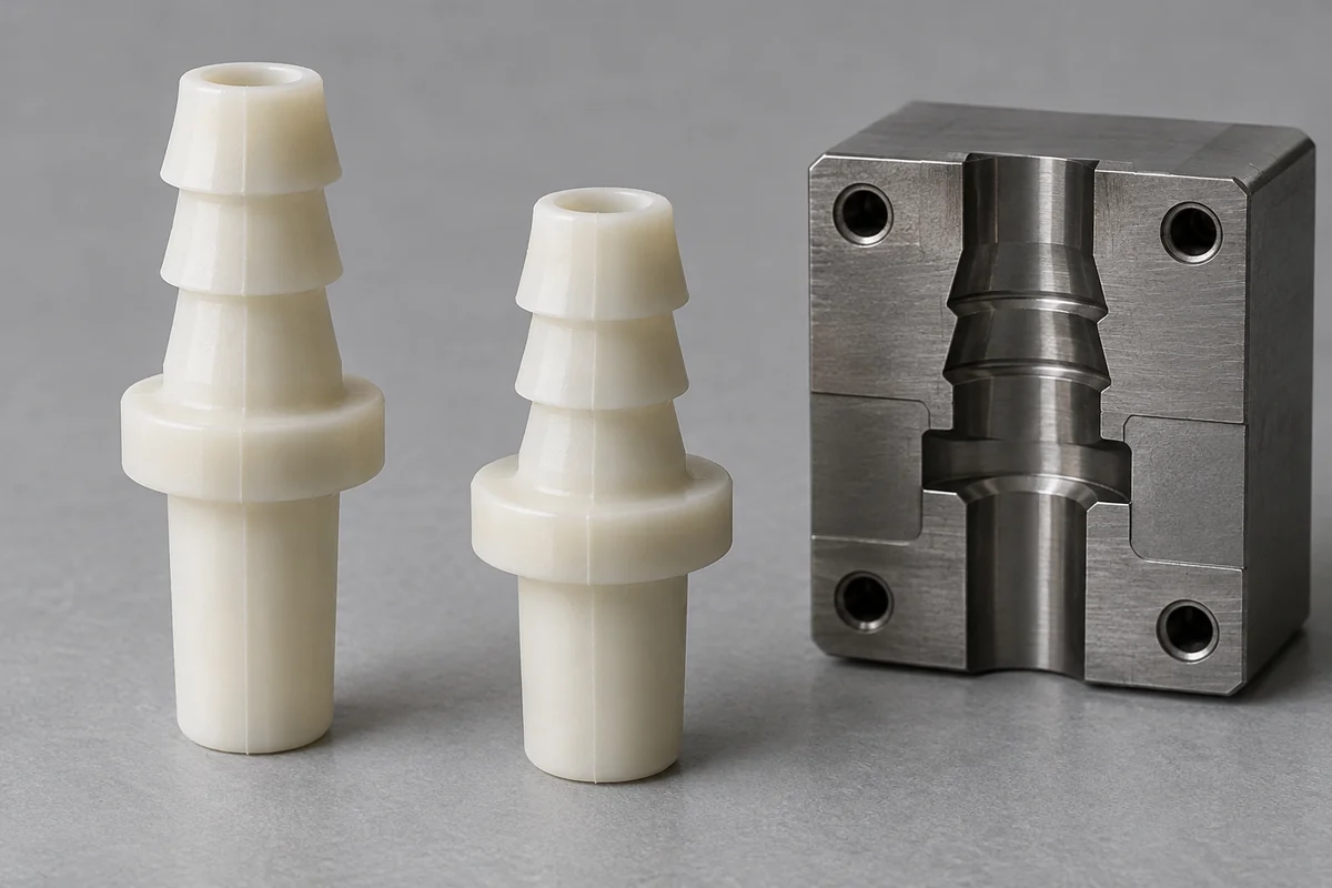
The early trial record identified flash around the barb-root and parting region, with concern about damage to the tube interior during assembly. Three of the eight cavities also produced a reported barb diameter of approximately 6.42 mm, below the drawing's lower limit. The record described low early pull-off readings of 35–42 N.
These observations were related but not interchangeable. A cleaner edge would not alone correct an undersized ridge, while a corrected diameter would not necessarily remove unwanted flash. The review therefore addressed the functional surface and cavity-to-cavity geometry as separate acceptance questions.
The intake also described bore silver streaks and a material-handling adjustment during development. The available summary does not isolate the cause of that observation. It is not used here to claim that every POM grade requires a particular drying cycle or to prescribe a universal molding recipe.
Engineering Response
Refine the tool split and review the affected cavity feeds
The recorded tooling changes moved the relevant parting feature toward a nonfunctional region below the barb and refined the tube-contact finish. Gate openings associated with the three undersized cavities were also adjusted as part of the filling-balance review. The revised parts were then assessed against the critical profile and bore requirements.
The T1 trial took place on January 20, 2026. The project subsequently recorded drawing Revision A dated January 25 and tool acceptance on February 28. These dates are kept distinct: the later drawing issue is not treated as a document that already existed during the earlier trial.
Functional confirmation used a defined tubing assembly rather than a generic hose. The owner clarified that the tube was PU, 6 mm inside diameter and Shore A85, with approximately 1.5 mm wall thickness and 9 mm outside diameter. Insertion depth was 10 mm and the pull rate was 50 mm/min. These conditions belong to this project's method.
Recorded Results
Keep the result connected to all eight cavities
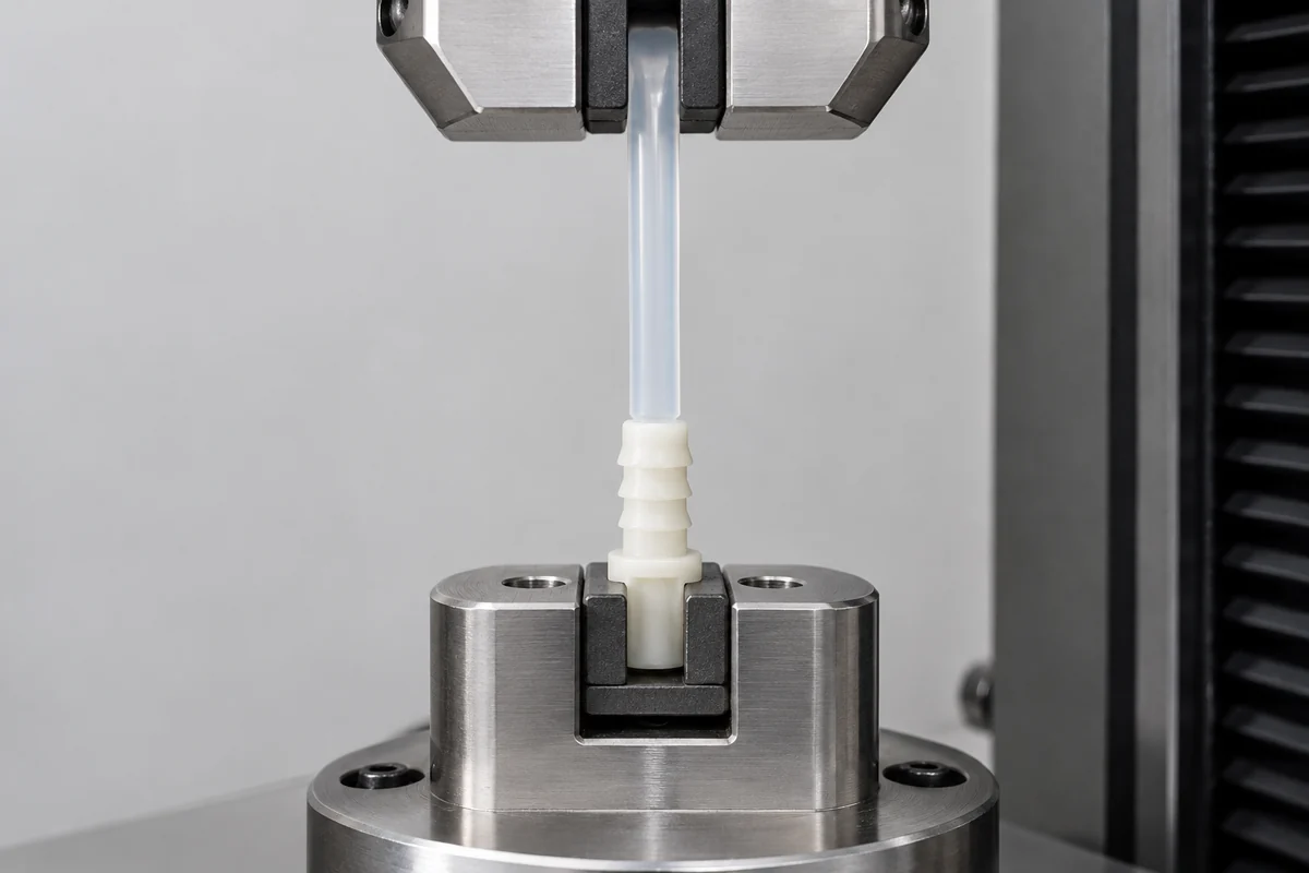
The confirmed T1 pull-off population was 24 specimens: three from each of the eight cavities. The reported individual results ranged from 62 to 78 N against the project's minimum requirement of 50 N. This clarified population supersedes the inconsistent sample counts in the initial intake.
The dimensional summary reported a 6.48–6.52 mm barb outside diameter and a 3.98–4.03 mm bore. These dimensional measurements have their own sampling records; they are not represented as measurements from the same 24 pull-off specimens. The trial summary also reported no visible flash on the inspected parts.
| Characteristic | Project requirement | Reported result | Recorded method or coverage |
|---|---|---|---|
| Barb outside diameter | 6.50 ± 0.05 mm | 6.48–6.52 mm | Optical measurement; intake specifies five pieces per cavity |
| Inner bore | 4.00 ± 0.05 mm | 3.98–4.03 mm | Reported optical measurement; separate dimensional record |
| T1 axial pull-off | At least 50 N | 62–78 N | 24 specimens: three per cavity across all eight cavities |
The early trial's sample definition is not sufficiently aligned with the clarified T1 population to support a precise improvement percentage. The case therefore reports the observed ranges and the accepted T1 requirement directly, without claiming a quantified reliability or defect-rate improvement.
Production and Scope
Carry cavity identity into repeat supply
Production deliveries began on March 10, 2026. The owner confirmed a cumulative delivered quantity of 85,000 pieces through September 2026. That is a delivery total, not the number of assemblies subjected to the T1 pull-off procedure or evidence that every delivered part was destructively tested.
The clarified repeat-production pull-off sampling was one part from each cavity, eight parts per batch. Keeping those identities made the inspection plan more specific than an unlabelled batch sample. Dimensional and appearance controls remained separate parts of the production quality scope.
Elevated-temperature retention and oil compatibility remained outside the confirmed result. The reported axial pull-off check does not establish leakage performance, long-term pressure life or suitability for other tubing. A different tube, assembly method or service environment requires its own review.
This anonymized case uses project records supplied and confirmed by FECISION for public use. Original inspection reports and project photographs are not reproduced here. The accompanying product design illustrations explain the component and inspection concepts; they are not evidence of measured results or delivered customer parts.
Related Engineering Guides
Prepare a defined hose-barb connection review
Review the fitting with its actual tubing.
Send the controlled drawing, tubing specification, service requirements and sample acceptance plan.
Request a Quote