
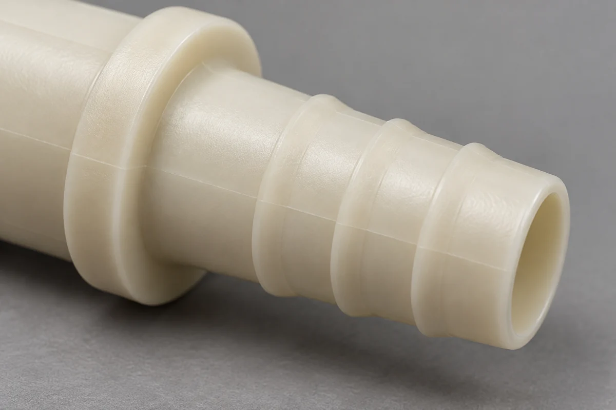
Product design illustrations. Final geometry, materials and acceptance criteria are project-specific.
A small seam on a molded hose barb is easy to dismiss as a cosmetic detail. At the tube-contact surface, however, the location and condition of that seam are functional questions. The tube must pass over the profile and remain in contact with the intended surface. A protruding edge, loose flash or misplaced gate vestige deserves a different review from a harmless visible witness.
The starting point is a clear description of what was observed. A parting line identifies where tool surfaces meet; flash is unwanted material extending into a gap. The two terms should not be used interchangeably. Calling every visible line flash can lead to unnecessary work, while accepting every seam as normal can leave a genuine assembly problem unaddressed.
Map the surfaces the tube actually encounters
Mark the leading nose, retaining ridges, valleys, engagement region and insertion stop. Show the direction of assembly and the final tube position. A feature outside the seated tube may still be crossed during insertion. That means an acceptance review should consider the assembly path, not just the surfaces touching the tube after it is fully installed.
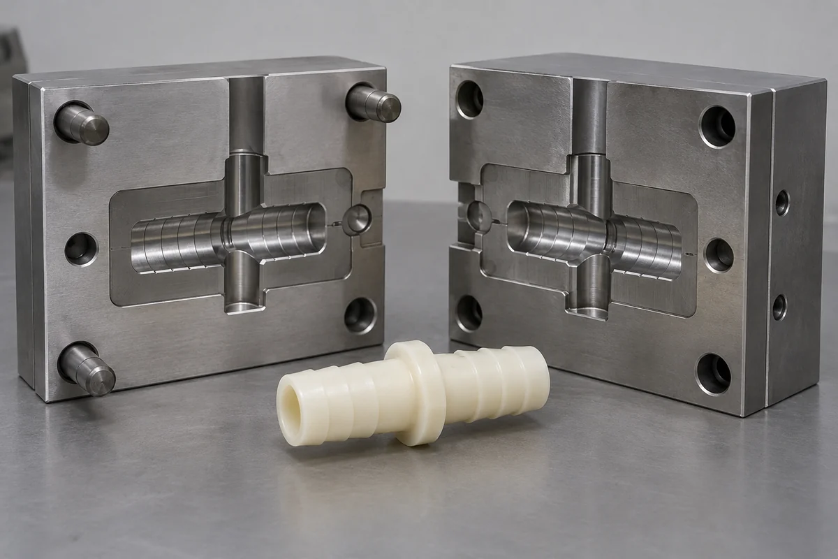
Review the available tool split with the mold designer. The practical options depend on the complete fitting shape, undercuts, bore and opposite-end geometry. Moving a split away from one critical region may create a different tooling or ejection issue elsewhere. The useful question is which arrangement can form and maintain the agreed functional surfaces reliably.
Distinguish the observed defect before correcting it
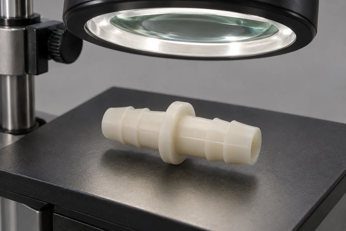
Inspect the edge at adequate magnification and record its location. Is it a thin protruding film, a mismatch between opposing surfaces, a gate vestige or a damaged ridge? Check whether the condition repeats on all cavities or follows a particular cavity. These observations help direct the investigation without treating every unwanted edge as the same manufacturing problem.
Compare identified parts from relevant points in the run where necessary. A persistent cavity-specific feature and an intermittent condition across the tool may lead to different questions. Preserve the sample and its process context. A photograph without cavity identity or trial stage can document appearance but may not explain where corrective work should begin.
Review tooling and process without assuming one cause
Tool alignment, shutoff condition and the filling or packing condition can all be part of the investigation. The molding team should assess the actual equipment and tool rather than apply a universal adjustment. Increasing clamp force or changing pressure is not automatically a complete correction, especially if it changes another critical characteristic or merely masks wear.
Likewise, polishing a tube-contact region is not a substitute for resolving an unwanted gap or mismatch. Define which surface is being changed and what geometry must remain. Removing material indiscriminately can alter a retaining profile that was already dimensionally correct. Tool maintenance and product acceptance should refer to the same controlled features.
Define appearance acceptance in functional terms
Agree how parts will be examined, including the viewing condition and any magnification. If a numeric limit is necessary, define the feature and measurement method. Where a visual standard is more useful, use approved examples with clear boundaries. A phrase such as no sharp edges is difficult to enforce consistently when neither the inspection condition nor the edge location is specified.
Keep bore cleanliness in the review. A connector can have an acceptable external seam while material or debris remains in the flow path. State whether trimming is permitted and how loose material is controlled afterward. Do not assume that an external visual inspection confirms every inaccessible internal surface or establishes a particular cleanliness classification.
If secondary trimming is proposed, assess its repeatability and effect on the contact surface. A hand-corrected development sample may not represent ordinary production. The quotation and control plan should identify the operation and its acceptance checks. Otherwise, a favorable sample can hide work that is not included in the repeat supply route.
Connect surface inspection to assembly evidence
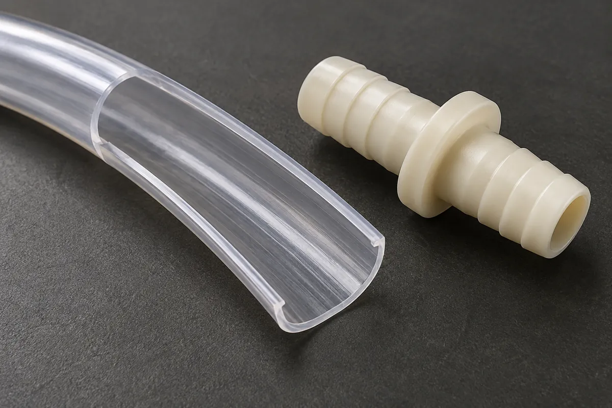
Use the specified tubing and controlled insertion method to evaluate the revised fitting. Inspect both the fitting and the tube after assembly where the procedure allows it. A damaged tube interior can help explain an assembly concern, but the assessment should distinguish actual damage from marks introduced during disassembly or sectioning for inspection.
Repeat the relevant dimensional and functional checks after a tool correction. The revised edge condition may be better while another feature has moved. Our cavity-resolved inspection guide explains why samples should retain their cavity identity rather than being combined into one apparently reassuring average.
Do not claim that a visually clean profile proves leak resistance or long-term retention. Those are separate evaluations with their own conditions and acceptance criteria. A surface correction can remove an identified risk without completing every required connection test. Report what was checked and keep any untested duty outside the resulting claim.
A robust release joins the controlled tool condition, the accepted fitting geometry, a practical surface standard and the agreed assembly evidence. This gives production a repeatable basis for inspection and maintenance. It also makes a later complaint more diagnosable because the team can compare the actual feature against a defined reference instead of debating whether the seam merely looks normal.
Review your custom hose connection
Explore our custom injection-molded hose barb fittings and the POM hose-barb retention case study. Send the fitting drawing, exact tubing specification, assembly conditions and acceptance requirements so that the quotation covers a defined part and inspection scope.