
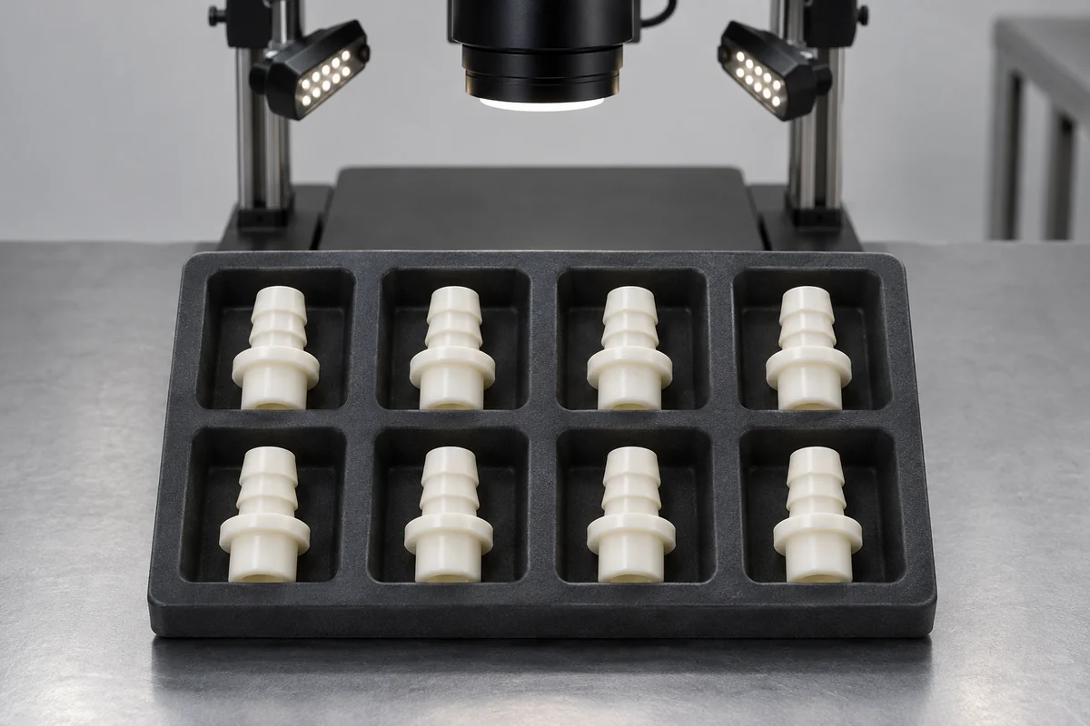
Product design illustrations. Final geometry, materials and acceptance criteria are project-specific.
A pooled inspection result can hide a cavity-specific problem. If most cavities produce acceptable hose barbs while one produces a different ridge profile, averaging their dimensions does not correct the affected parts. Cavity identity makes that variation visible. It connects a product measurement to a tool location that the manufacturing team can investigate and control.
This is especially useful when a small profile dimension influences tube assembly. The fitting's bore, ridge and surface condition all matter, but they may not vary in the same way. An inspection plan should identify the functional characteristics and keep their records connected to the cavity, drawing revision and relevant production stage.
Start with the accepted connection geometry
Mark which dimensions control the tube interface and which describe other functions. Define the ridge location to be measured, the bore features and any important concentricity or mounting reference. Avoid asking inspection to infer the intended feature from a generic barb diameter label. A clear drawing is more useful than a long list of poorly defined measurements.
Specify when parts are inspected and how they are conditioned. The Delrin molding guide discusses dimensional behavior after molding and the influence of processing conditions. For a POM fitting, use a consistent inspection state and evaluate the actual molded geometry rather than assuming one resin shrinkage value resolves every cavity.
Preserve identity from molding to the report
Agree how cavity identity will be retained without placing an unwanted mark on the functional surface. Molded identification, segregated collection or another controlled method may be appropriate. The method must work through sample preparation and reporting. A tray that begins correctly organized is not sufficient if parts become mixed before the measurements are recorded.
Record the tool and drawing revision, resin identification and trial or lot reference with the sample. Include the timing within a run when it matters to the investigation. That allows the team to distinguish a persistent cavity difference from a change associated with a particular production period or an uncontrolled sample-handling condition.
Use a method that resolves the functional profile
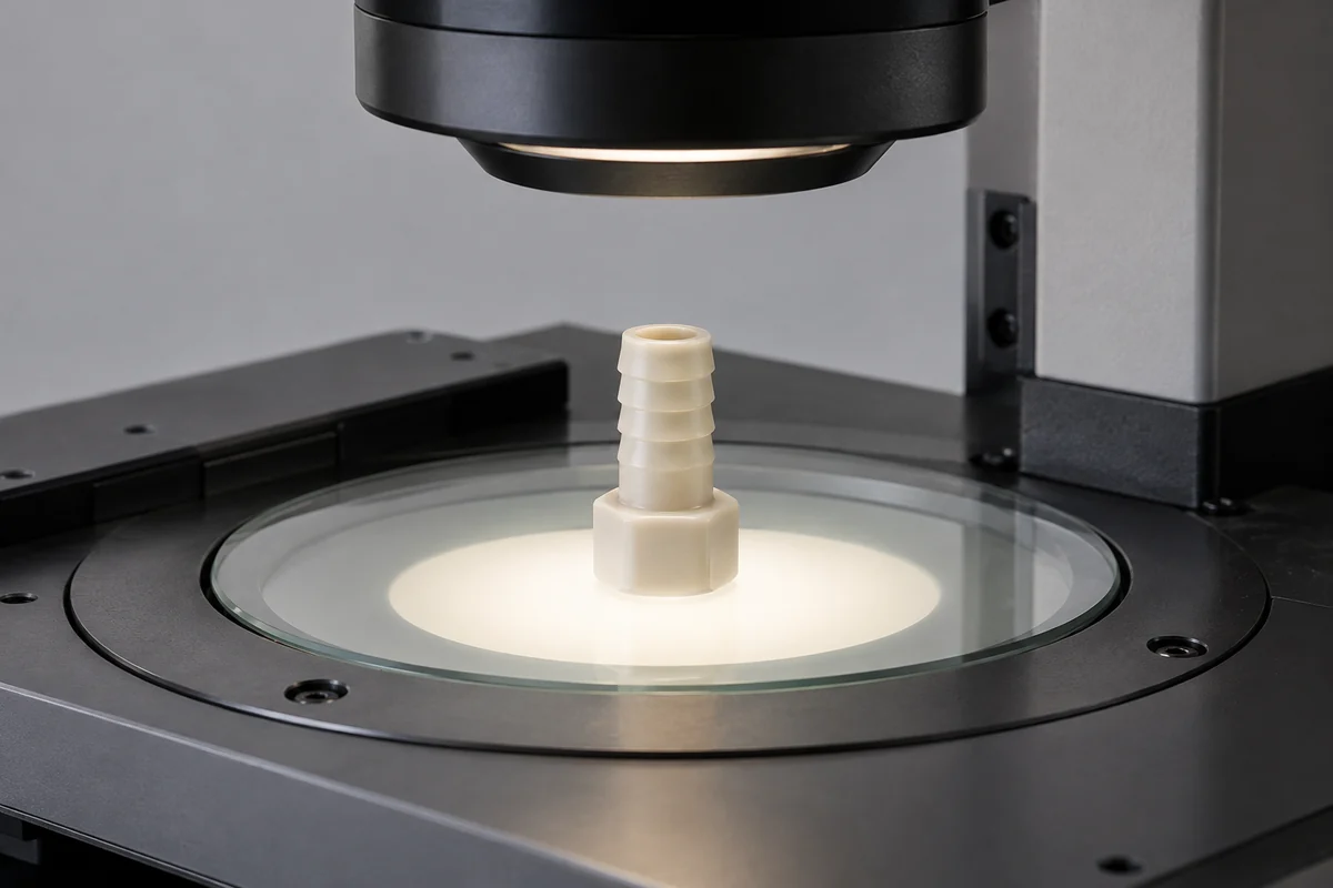
Choose measurement access and fixturing appropriate to the feature. A flexible or small part may need support that does not distort it, and a ridge may need an optical profile rather than an ambiguous contact reading. Define how the sample is aligned. The instrument name alone does not describe which geometry the operator actually measured.
Evaluate the measurement system against the tolerance and the intended decision. If repeated readings vary because the profile is difficult to locate, a larger sample count does not remove that uncertainty. Resolve the method before drawing a strong conclusion from small differences between cavities. Keep any measurement limitation visible in the report.
Investigate differences without overinterpreting averages
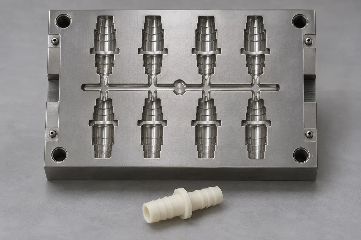
Review individual results and cavity-level patterns. If one cavity is consistently different, assess its relevant tool and process conditions rather than adjusting the whole mold solely to improve the overall mean. The investigation may involve local geometry, flow balance or thermal conditions. The actual evidence should guide the explanation; a pattern does not by itself prove its cause.
After a change, recheck the affected feature and the other critical characteristics. A gate modification intended to improve one ridge dimension may influence another part of the fitting. Keep the before-and-after sample definitions clear. If multiple changes were made together, report the observed outcome without claiming that one isolated adjustment explains all of it.
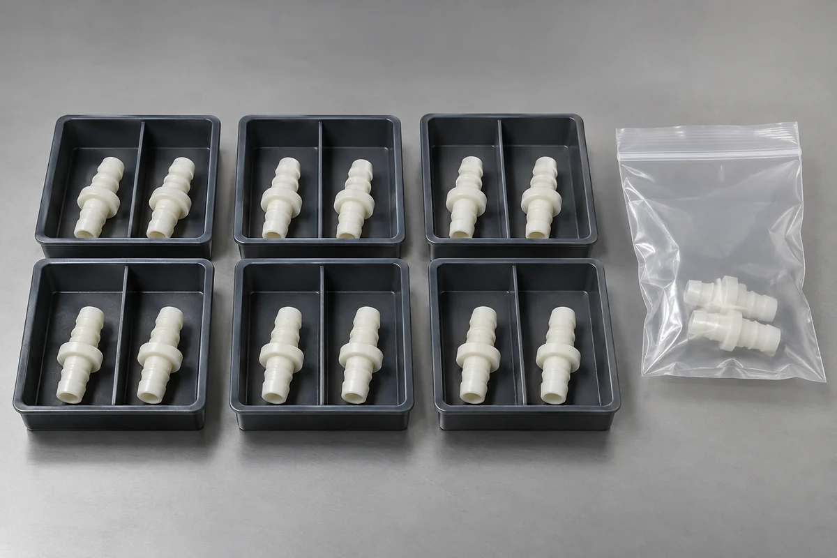
Do not calculate capability from an inadequate or unrepresentative sample set. A range from a few trial parts can document those observations, but it is not automatically evidence of a stable production distribution. Capability or defect-rate claims require a suitable measurement system, sampling basis and analysis. The article's compartment-tray illustrations do not constitute such evidence.
Link dimensions to surface and assembly checks
Keep flash, gate vestige and bore condition in the acceptance plan. A dimensionally correct fitting can still have an unacceptable tube-contact edge. Define the inspection conditions and any approved visual references. Our flash and parting-line guide explains why these observations should remain distinct from a simple diameter measurement.
Where retention is a requirement, define cavity coverage for the assembly specimens as well. A dimensional report and a pull-off report should be traceable to their respective sample populations. Do not assume that a small unlabelled pull-off group demonstrates equivalent performance across every cavity because the separate dimensions looked similar.
Make development and repeat-production sampling separate decisions. Trial work may use a detailed all-cavity review; the approved control plan should state the repeat sampling, frequency and response to nonconformance. Do not copy a development sample count into production without explaining what it is intended to detect and how an issue will be contained.
Finally, connect tool maintenance and material changes to the inspection plan. A repaired cavity or revised resin can require renewed checks even when the product number stays the same. Clear change triggers preserve the meaning of the original approval. The goal is a controlled connection geometry from each active cavity, supported by evidence that remains useful after the first trial.
Review your custom hose connection
Explore our custom injection-molded hose barb fittings and the POM hose-barb retention case study. Send the fitting drawing, exact tubing specification, assembly conditions and acceptance requirements so that the quotation covers a defined part and inspection scope.